13-Pin Plug Wiring Diagram (ISO 11446)
This is a free printable 13 pin plug wiring diagram: download the diagram as SVG or open it and print to paper or PDF.
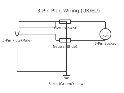
Wire a 13-pin trailer or caravan plug correctly using the ISO 11446 standard pin assignments for lights, reversing, refrigerator, and battery charging circuits.
The 13-pin round connector defined by ISO 11446 is the standard coupling used on caravans, horse boxes, and heavy trailers throughout Europe and increasingly in other markets. It supersedes the older separate 7-pin combinations (N-type and S-type plugs) by combining all trailer electrical functions into a single robust connector.
The 13 pins are arranged in a circular pattern and divided into functional groups. Pins 1–8 replicate the functions of the legacy 7-pin N-type connector: pin 1 is left-turn indicator (yellow), pin 2 is rear fog lamp (blue), pin 3 is earth/ground for the indicator and lighting circuits (white), pin 4 is right-turn indicator (green), pin 5 is right-side lights and tail lamp (brown), pin 6 is brake lights (red), and pin 7 is left-side lights and tail lamp (black). Pin 8 is reversing lamp (pink/grey).
Pins 9–13 provide the additional functions previously carried by the S-type auxiliary connector. Pin 9 is a permanent +12V supply for the caravan battery charging circuit (typically white/red or orange). Pin 10 is the switched +12V supply that activates when the ignition is on, used to power the caravan's 12V refrigerator in transit (yellow/brown or blue). Pin 11 is the earth return for pins 9 and 10 (white/black). Pin 12 is the coded or spare function, used for electronic brake controllers in some markets. Pin 13 is the earth for pin 12 (yellow/green).
Connector bodies are typically manufactured in plastic with a weather-resistant sealing gland and a positive-locking mechanism. The vehicle-side fitting is the socket (female); the trailer or caravan side is the plug (male). Always verify pin assignments against the vehicle's towing electrics wiring diagram, as minor variations exist between manufacturers for pins 9–13.
How to wire 13 pin plug wiring diagram
- Identify pin 1 position on the connector The 13-pin connector body has pin 1 marked by a moulded number, a larger pin, or an index notch on the connector housing. With the connector face toward you (as you would view it when mating), pin 1 is typically at the top-left. Confirm against the connector manufacturer's datasheet or the ISO 11446 diagram.
- Strip and prepare the wiring harness Slide the connector body collar and cable gland onto the cable before terminating any wires. Strip the outer sheath back 60–80 mm. Strip each individual wire 6–8 mm. Twist and tin each core if using soldered pins, or ensure a clean, unfrayed end for crimp-type contacts.
- Terminate pins 1–8 (lighting functions) Connect each wire to the correct pin per ISO 11446 assignment: pin 1 left indicator, pin 2 rear fog, pin 3 earth/return, pin 4 right indicator, pin 5 right tail, pin 6 brake, pin 7 left tail, pin 8 reversing lamp. Use the specific colour code documented for your harness, not a generic assumption.
- Terminate pins 9–13 (auxiliary functions) Connect pin 9 to the permanent 12V supply (battery charging), pin 10 to the ignition-switched supply (refrigerator/leisure), pin 11 to the dedicated earth return for pins 9–10. Wire pin 12 if a brake controller or coded function is fitted. Connect pin 13 as earth for pin 12 where applicable.
- Assemble and seal the connector body Draw the wires through the cable gland and seat each pin firmly into the connector body until it clicks or locks. Ensure no wire insulation is pulled back from the contact. Tighten the gland nut to compress the seal around the cable jacket. Fit the protective cap to the mating face when the trailer is disconnected.
- Test all circuits before use Connect to the vehicle towbar socket and test each function in turn: left and right indicators (including hazard), brake lamps, rear fog, tail lights, reversing lamp, and auxiliary supplies (check pin 9 voltage with a multimeter). Correct any non-functional circuit before towing.
Specifications
| Standard | ISO 11446 (13-pin motor vehicle and trailer electrical connector) |
|---|---|
| Connector type | 13-pin round, male plug (trailer) and female socket (vehicle) |
| Operating voltage | 12V DC nominal (vehicle electrical system) |
| Current rating per contact (typical) | 10 A for lighting pins; 15–20 A for auxiliary supply pins 9 and 10 (verify with connector manufacturer) |
| Pin 3 function | Main earth return for pins 1, 2, 4, 5, 6, 7, 8 (lighting and indicator circuits) |
| Pin 9 function | Permanent +12V for caravan battery charging |
| Pin 10 function | Ignition-switched +12V for in-transit refrigerator supply |
| IP rating (typical weatherproof housing) | IP54 or IP65 depending on manufacturer and cap fitted |
Safety warnings
- Disconnect the tow vehicle battery before working on towbar wiring to prevent accidental short circuits across shared lighting and supply circuits. Even with the ignition off, lighting circuits may be live.
- The permanent 12V supply on pin 9 is live at all times regardless of ignition state. Ensure all wiring on this circuit is correctly fused and insulated to prevent fire risk during storage or when the trailer is parked.
- Never exceed the current rating of the connector contacts — overloading can cause heat buildup at the connector, melting the housing and creating a fire risk. Size fuses conservatively and use the correct wire cross-section for each circuit.
- This wiring diagram is provided as an illustrative reference only. Verify pin assignments and colour coding against your specific vehicle's towing electrics documentation and the harness manufacturer's instructions. An incorrectly wired trailer plug can result in missing brake lights — a serious road safety hazard.
- Where towing regulations apply in your jurisdiction, ensure the electrical installation meets the required standard (e.g., Directive 94/20/EC in Europe) and that trailer lighting is verified by a competent person before the vehicle is used on public roads.
Tools needed
- Multimeter (DC voltage and continuity functions)
- Wire strippers (sized for harness conductors)
- Crimping tool for automotive insulated terminals
- Screwdrivers (for connector body assembly)
- Cable ties and loom tape
- Soldering iron and solder (if using solder-type pin contacts)
- Circuit tester or automotive test lamp
Common mistakes
- Mixing up pin 3 (lighting earth) and pin 11 (auxiliary earth): These must remain separate. Combining them can cause charging current to flow through the lighting earth, creating voltage drop that causes indicator and brake lamp faults.
- Not seating the cable gland correctly: A loose gland allows moisture ingress into the connector body, causing corrosion on the contacts and intermittent circuit faults — the most common cause of trailer electrical problems.
- Assuming wire colours are standardised: ISO 11446 does not mandate wire colours. Different harness manufacturers use different colour schemes. Always trace the wire back to its source or use a multimeter to verify before making assumptions.
- Omitting fuses on auxiliary supply circuits: Pins 9 and 10 carry unfused current from the vehicle battery if not protected. A short circuit in the caravan 12V system can draw enough current to cause a fire in the vehicle wiring.
- Forgetting the protective cap: The 13-pin socket on the vehicle is exposed to road spray and dirt when not in use. Without the protective cap, water and debris enter the socket, corroding contacts and causing the first connection after a period of non-use to fail.
Troubleshooting
- Trailer indicators work but brake lights do not
- Cause: Open circuit on pin 6 (brake lamp circuit) — broken wire, corroded contact, or failed vehicle brake light switch signal to towbar wiring Fix: Measure voltage at pin 6 of the vehicle socket with the brake pedal depressed. If no voltage, trace back to the tee-in point on the vehicle stop lamp circuit. If voltage is present at the socket but not at the trailer, inspect the plug contact and wiring continuity.
- Caravan battery not charging via pin 9
- Cause: Vehicle towbar electrics kit does not include an active pin 9 output, or the relay/BCM output supplying pin 9 is not functioning Fix: Measure voltage at pin 9 with the engine running. If absent, confirm whether the vehicle's towbar electrics kit includes a pin 9 (battery charging) output — many basic kits do not. An external relay or battery-to-battery charger installation may be required.
- Intermittent loss of all trailer lighting
- Cause: Corroded or damaged pin 3 (main earth) contact in the plug or socket Fix: Clean the plug and socket contacts using an appropriate electrical contact cleaner. Check continuity of pin 3 back to the vehicle chassis. If the contact is physically damaged or the socket is heavily corroded, replace the plug or socket. Apply a thin layer of dielectric grease to protect cleaned contacts.
Frequently asked questions
What is the difference between a 7-pin and a 13-pin trailer plug?
A 7-pin N-type connector carries only the basic lighting functions (indicators, brake, tail, fog, earth). The 13-pin ISO 11446 connector carries those same functions on pins 1–7, plus reversing lamp (pin 8), battery charging (pin 9), refrigerator supply (pin 10), and auxiliary earths on pins 11–13 — all in a single connector.
Which pin is the earth on a 13-pin trailer plug?
Pin 3 is the main earth return for the lighting and indicator circuits (pins 1, 2, 4, 5, 6, 7). Pin 11 is the separate earth for the battery charging and refrigerator circuits (pins 9 and 10). Pin 13 is the earth for the coded/auxiliary function on pin 12. Using separate earths prevents lighting interference on sensitive circuits.
Can I connect a 7-pin trailer to a 13-pin socket on my vehicle?
Yes — an adapter is used. The adapter mates a 7-pin N-type plug into the 13-pin socket and maps pins 1–7 to the corresponding positions. Pins 8–13 on the socket remain unconnected. This is the standard approach for light trailers that only use basic lighting functions.
Why does my caravan battery not charge when connected via the 13-pin plug?
Pin 9 should provide a permanent 12V supply for battery charging, but many tow vehicles only activate this pin when the engine is running (via a battery-to-battery charger relay). Check that the vehicle's towbar electrics include an active pin 9 output — not all factory-fit towbar kits include this circuit.
What colour is each wire in a 13-pin trailer wiring harness?
Colour coding varies by manufacturer and country of origin. ISO 11446 defines pin function, not wire colour. Common conventions include white for earth (pin 3), yellow for left indicator (pin 1), green for right indicator (pin 4), red for brake (pin 6), brown for right tail (pin 5), and black for left tail (pin 7). Always verify against the specific harness documentation.
Related diagrams
- 13 pin trailer plug wiring diagram
- 12 pin caravan plug wiring diagram
- 12 pin plug wiring
- 12 pin trailer plug wiring
- 13 pin socket wiring diagram
- 13 pin trailer wiring diagram