Wiring Diagram Software
Wiring diagram software shows how devices and terminals are connected, then turns those connections into documentation people can build, inspect, and revise. CircuitDiagramMaker combines an editable browser canvas with terminal-aware wires, automatic right-angle routing, device and wire data, live schedules, and review tools. It opens without a download, while saved projects and collaboration use an account.
Product scope reviewed: 2026-07-30. This is a first-party capability review, not an independent engineering certification.
- placeable electrical symbols
- 480+
- live engineering reports
- 10
- desktop downloads required
- 0

Use the right electrical drawing for the job
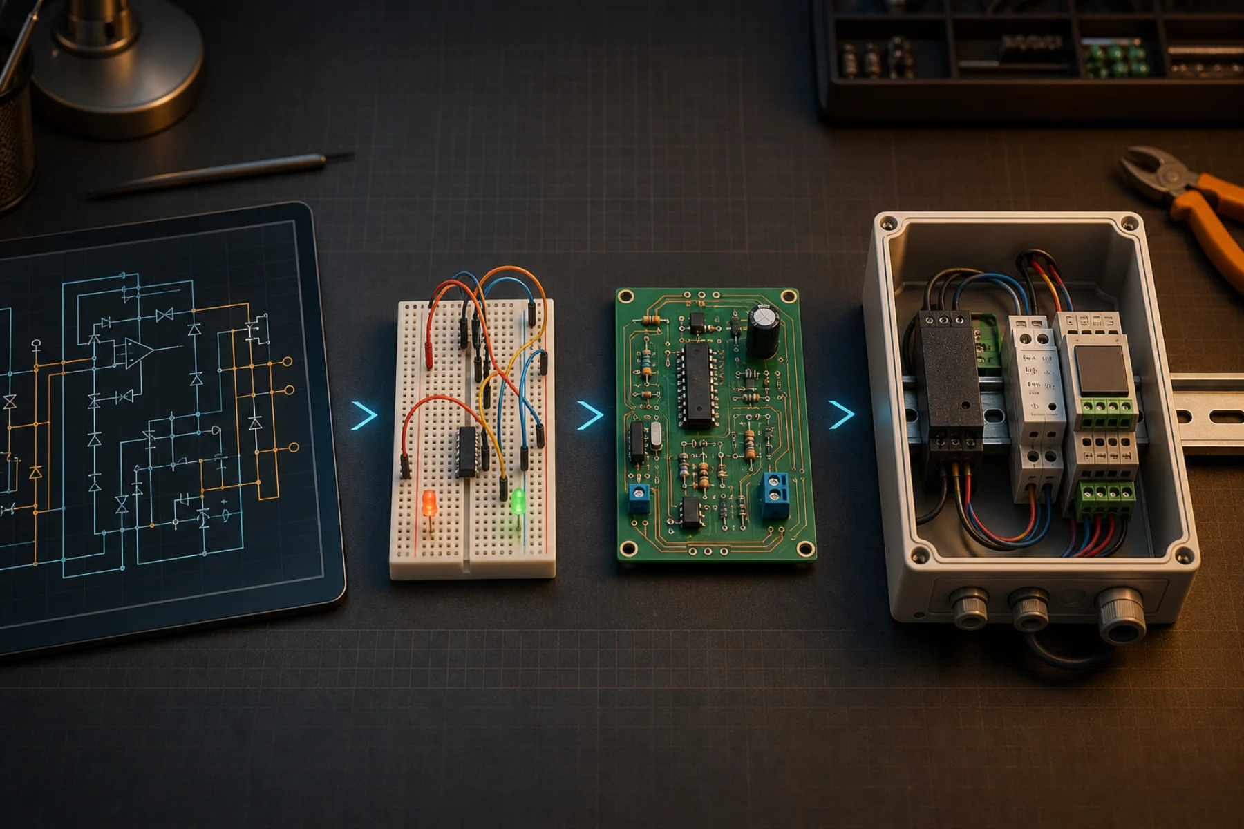
A schematic emphasizes electrical function, a wiring diagram exposes actual conductors and terminals, a single-line diagram simplifies a distribution system, and a panel layout shows physical mounting. The workspace keeps these purposes distinct while allowing shared device data to move between compatible views.
- Wiring and connection diagrams with explicit terminal endpoints
- Functional circuit schematics using electrical and electronic symbols
- Single-line documents for sources, protection, feeders, and loads
- Two-dimensional and synchronized three-dimensional control-panel layouts
Draw clean connections without fighting the canvas
Connections snap to registered pins and can be routed as editable Manhattan paths. Junction dots distinguish connected branches from crossings, while wire numbers, net labels, colors, gauges, and off-page connectors make larger drawings easier to follow. Automatic routing is a starting point: every route remains adjustable.
- Pin-to-pin snapping and terminal-aware endpoints
- Right-angle routing with manual jog handles
- Junctions, crossings, net highlighting, and off-page connectors
- Grid, rulers, layers, minimap, alignment, and multi-select tools
Keep drawing objects tied to engineering data
A line drawing becomes more useful when the devices and conductors carry structured data. Components can store tags, descriptions, values, manufacturer details, catalog numbers, terminals, physical dimensions, mounting, PLC addresses, and custom fields. Wires can store from-to endpoints, color, gauge, cable/core, length, slack, and termination information.
- Reusable project device records and custom physical profiles
- Live device, BOM, wire, cable, terminal, load, and PLC I/O schedules
- CSV import for device, cable, and terminal data
- Cross-sheet find and replace for identifiers and descriptions
Check what software can check—and expose the boundary
Deterministic checks identify missing or duplicate tags, orphan conductors, duplicate wire numbers, missing sizes, incomplete source paths, unprotected loads, and selected voltage or phase mismatches. Supported circuit models can run DC, transient, and AC analysis. Neither check is a substitute for manufacturer instructions, regional code review, or professional sign-off.
- Repeatable structural and topology checks
- Simulation compatibility published by model and analysis type
- Visible issue severity and affected drawing object
- No hidden claim of general SPICE or code compliance
Export something another person can actually use
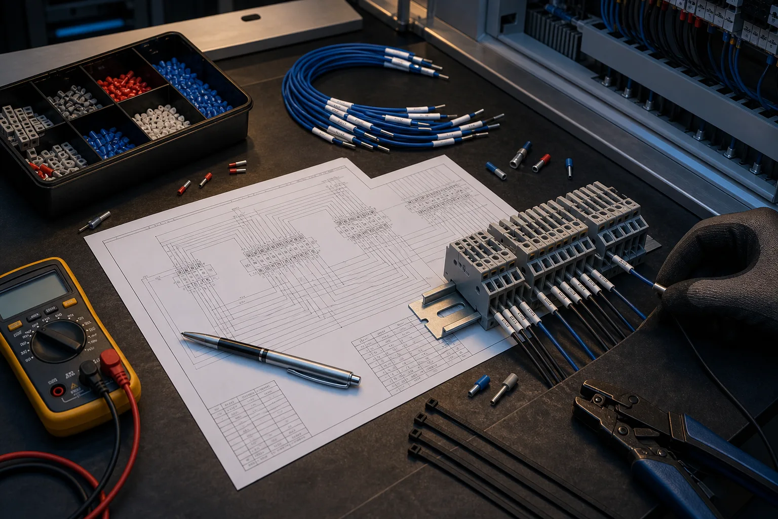
The same project can produce a print-ready drawing and the tabular records needed for estimating, review, assembly, commissioning, or maintenance. Version history, anchored comments, revision comparison, and immutable releases help teams distinguish an issued package from the next edit.
- PDF, SVG, PNG, and DXF drawing outputs
- BOM and ten live schedule types in CSV
- Share links, role-based collaboration, and anchored review notes
- Sequential releases with a content hash and preserved snapshot
Workflow
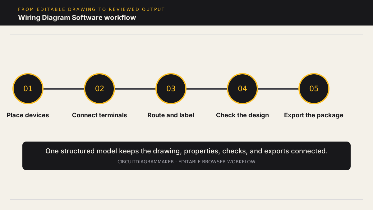
- Choose a starter template or place electrical, electronic, industrial, connector, and power symbols on a clean multi-sheet canvas.
- Connect real component terminals with pin-to-pin snapping, junctions, off-page connectors, net labels, and editable right-angle routes.
- Add device tags, manufacturer and catalog data, wire numbers, colors, gauges, cable cores, terminals, locations, and custom fields.
- Run deterministic connectivity and documentation checks and, for supported component models, DC, transient, or AC circuit analysis.
- Export the drawing as PDF, SVG, PNG, or DXF and export synchronized BOM, wire, cable, terminal, load, PLC I/O, and label schedules as CSV.
Deliverables
- Editable drawing: Multi-sheet terminal-aware wiring with layers, labels, notes, title blocks, and reusable symbols.
- Build schedules: Device/BOM, wire, cable, terminal, label, splice, load, PLC I/O, and cross-reference CSV reports.
- Review evidence: Issue results, comments anchored to objects, revision comparison, version history, and immutable releases.
- Handoff files: PDF, SVG, PNG, DXF, project JSON, and supported-model netlist output with explicit scope limits.
Current limitations
- Reference diagrams and automated checks are not installation approval. Verify conductor sizing, protection, ratings, and regional code requirements with authoritative sources and a qualified professional.
- Circuit analysis supports a documented subset of models and DC, transient, or AC cases; it is not drop-in compatibility with arbitrary SPICE models or subcircuits.
- PCB Lite and 3D panel visualization support bounded documentation workflows; they do not claim KiCad-class PCB fabrication depth or STEP/Parasolid MCAD exchange.
Capability sources
- Product capability matrix
- Simulation model compatibility
- Physical component library and verification states
Related electrical design workflows
Frequently asked questions
Can I use the wiring diagram software for free?
Yes. Create a free account to open the editor in your browser without a download. Saving, sharing, advanced packs, exports, and other capabilities are subject to the current account and plan limits shown on the pricing and capability pages.
What is the difference between a wiring diagram and a schematic?
A schematic emphasizes circuit function using standardized symbols. A wiring diagram normally shows the conductors, terminals, connectors, wire identifiers, and physical connection details needed to build or service the system.
Does the software automatically route wires?
It can create right-angle routes between registered terminals and avoid basic obstacles. The route remains editable, and the designer must still confirm readability and electrical intent.
Can the software test a wiring diagram?
It runs deterministic connectivity and documentation checks. Supported electrical models can also run DC, transient, or AC analysis. The simulation compatibility matrix lists the exact boundaries.
Which files can I export?
Drawing outputs include PDF, SVG, PNG, and DXF. Structured outputs include project JSON and CSV reports for devices, wires, cables, terminals, loads, PLC I/O, labels, splices, and cross-references. Plan limits apply.
Open a motor-starter sample or review the capability matrix.