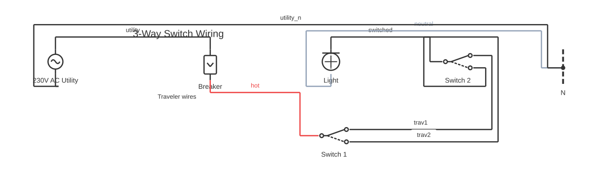
3-Way Switch Wiring — How to Wire Two Switches to One Light
This is a free printable 3 way switch wiring: download the diagram as SVG or open it and print to paper or PDF.
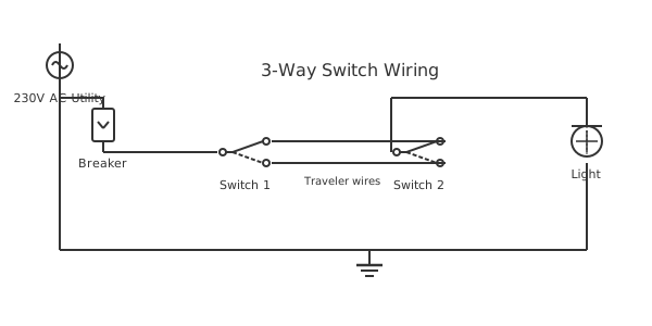
3-way switch wiring allows a single light (or group of lights) to be controlled from two separate locations — typically both ends of a hallway, stairway, or large room. Understanding how three-way switches work and how to wire them correctly is one of the most common electrical challenges for DIYers and apprentice electricians. This guide explains the circuit, the wiring methods, and how to troubleshoot common problems.
A three-way switch differs from a standard single-pole switch by having three terminals instead of two: a COMMON terminal (usually marked COM or darker in color) and two TRAVELER terminals. The switch connects the common to one traveler or the other, but never both simultaneously — it's essentially a single-pole double-throw (SPDT) switch. The light is controlled by the relationship between both switches, not by either switch alone.\n\nIn the basic three-way circuit, the hot (black) wire from the power source connects to the COMMON terminal of the first switch. The two traveler terminals of switch 1 connect via two conductors (the traveler wires) to the two traveler terminals of switch 2. The COMMON terminal of switch 2 connects to the hot terminal of the light fixture. Neutral connects directly from the source to the neutral terminal of the fixture without passing through either switch.\n\nThe circuit works because: regardless of how the first switch is set, flipping the second switch always changes which traveler is connected to the light's common, toggling the light. When both travelers are at the same potential (both commons on the same leg), the light is on. When they are on different legs, the light is off. Or vice versa, depending on your exact switch toggle positions.\n\nIn NEC-compliant modern wiring, where power enters at the light fixture box rather than at the first switch, a 14-3 or 12-3 cable (with black, white, red, and bare conductors) runs between the two switch boxes. The white wire is re-identified as a hot conductor by wrapping with black tape since it carries hot potential, not neutral. This alternative wiring method requires understanding which wire plays which role.\n\nWith LED fixtures on three-way circuits, a ghost voltage phenomenon can cause LEDs to glow dimly when they should be off. This occurs because the floating traveler wire capacitively couples enough voltage to the LED driver to illuminate it slightly. Adding a small resistive load (a watt-stopper or a 10 W incandescent in parallel) or using LED bulbs rated for three-way use resolves this.
Power-at-Switch vs Power-at-Light: Which Configuration Do You Have?
The most important variable in any 3-way switch job is where the incoming line power enters the circuit. In the power-at-switch (standard) configuration, a 14-2 NM-B cable carries the line hot and neutral into the first switch box (SW1). A 14-3 NM-B cable then runs from SW1 to the second switch (SW2), carrying the two traveler wires (red and black) plus a white neutral. A separate 14-2 cable runs from SW2 to the fixture. The black (line hot) of the 14-2 feed lands on SW1's COM terminal — the dark-coloured screw. At SW2, the black of the outgoing 14-2 cable lands on SW2's COM terminal, completing the switched-hot path to the fixture.
In the power-at-light configuration, the 14-2 power feed enters the fixture box instead. A 14-3 cable runs from the fixture to SW2, then another 14-3 (or a second run) continues to SW1. Because there is no spare wire to carry the line hot directly, the white of the first 14-3 cable is re-identified with black electrical tape at both ends and used as the hot conductor — this is an NEC requirement, not optional. SW2's COM receives this re-identified white (line hot); SW1's COM sends the switched-hot back to the fixture. Neutral wires bypass all switch terminals entirely and splice through with wire nuts.
Adding a Dimmer to a 3-Way Circuit
Only one dimmer is permitted per 3-way circuit. The second switch location must remain a standard 3-way switch. Install the dimmer at the switch where the line hot enters the COM terminal for the most consistent performance, though most modern dimmers auto-detect line vs load side. Before buying, check whether the dimmer requires a neutral wire — smart dimmers and most LED-rated dimmers need a white neutral in the box. If no neutral is present, choose a rated no-neutral compatible model. Use only dimmable LED, incandescent, or halogen bulbs; standard (non-dimmable) LEDs, smart bulbs, fluorescent tubes, and ceiling fans are not compatible. LED flicker at the low end is usually solved by selecting a dimmer certified for LED loads and adjusting the internal low-end trim screw.
Wiring Two Lights on a 3-Way Circuit
Additional fixtures wire in parallel on the load side. Run 14-2 NM-B from the first fixture's junction to each additional fixture, connecting black-to-black (switched-hot) and white-to-white (neutral). No changes to the switch boxes or the 14-3 traveler cable are required — the 3-way switching logic is entirely in the two switch boxes. On a 15A circuit the total load must stay below 1,440W; with modern LED bulbs at 8–12W each this limit is rarely reached.
UK Colour Code and Terminal Naming vs US
In UK wiring (BS 7671 / 18th Edition), what Americans call a 3-way switch is called a two-way switch, and it has three terminals labelled COM, L1, and L2. COM receives the permanent live at the first switch and the switched live (to the lamp) at the last switch. L1 and L2 are the strapper conductors — equivalent to the US traveler wires. The cable between switches is 3-core-and-earth using brown, grey, and black cores plus a green-yellow earth. In older pre-2004 UK installations the colours were red (live), yellow, and blue — always sleeve any repurposed conductors with the correct sleeving to comply with the 18th Edition. The intermediate switch (4-terminal L1/L2/L3/L4) is the UK equivalent of a US 4-way switch and must be used whenever a third control point is needed. Never substitute a two-way switch for an intermediate switch.
Three-way switch wiring allows a light to be controlled from two separate locations — a common requirement for stairways, hallways, and large rooms. The method varies depending on where the supply power enters: at the first switch box, at the second switch box, or at the light fixture itself. UK installations use a different terminal naming convention (L1, L2, COM) and ring/radial cable colours (brown live, blue neutral, grey and yellow/green for switch wires). Whether you are wiring with a dimmer, controlling two lights, or working through a specific brand like Kaish, drawing the circuit first prevents dangerous mis-wiring — use the free online editor to map your exact configuration.
How to wire 3 way switch wiring
- Turn off the breaker and verify zero voltage Switch off the circuit breaker and use a non-contact voltage tester at both switch boxes and the light fixture box to confirm all conductors are de-energized before proceeding.
- Run 14-3 cable between switch boxes Pull 14-3 NM cable (black, white, red, and bare ground) between the two switch locations. Also run 14-2 NM cable from the power source to the first switch box and from the second switch box to the light fixture, or configure for power-at-fixture as required.
- Wire the first 3-way switch Connect the hot (black) feed wire to the COMMON (dark) screw. Connect the two traveler wires (black and red from the 14-3 cable) to the two traveler (brass) screws. Connect the bare ground to the ground screw.
- Wire the second 3-way switch Connect the two traveler wires from the 14-3 cable (matching the colors used at switch 1) to the two traveler screws. Connect the wire going to the light fixture to the COMMON (dark) screw. Connect the bare ground to the ground screw.
- Connect the light fixture Connect the hot wire from the second switch COMMON to the fixture's black wire. Connect neutral from the source to the fixture's white wire. Connect the ground to the fixture's green screw or bare wire. Restore power and test both switches.
Specifications
| Cable Type (traveler run) | 14-3 NM-B (or 12-3 for 20 A circuits) |
|---|---|
| Switch Rating | 15 A, 120/277 VAC |
| Terminals per Switch | 3 (1 common + 2 travelers) |
| Wire Colors (travelers) | Black and red from 14-3 cable |
Safety warnings
- Turn off the circuit breaker and verify zero voltage with a non-contact tester at both switch boxes before touching any wiring.
- With power entering at the light fixture (switch loop wiring), all three wires in the cable to the first switch box carry hot potential at some switch position — test all wires before touching.
- Never connect the ground wire to the traveler terminals — the ground must connect to the ground screws on both switches and the fixture, completing the protective earth path.
Tools needed
- Non-contact voltage tester
- Digital multimeter for continuity testing
- Flathead and Phillips screwdrivers (insulated)
- 14-2 and 14-3 NM cable or 12-2 and 12-3 for 20 A circuits
Common mistakes
- Connecting a traveler wire to the COMMON terminal instead of a traveler terminal — the light will work from only one switch.
- Using a standard 14-2 cable for the traveler run — three-way wiring requires 14-3 cable with three insulated conductors plus ground.
- Not re-identifying the white wire as a hot conductor when used as a switch leg — NEC 200.7 requires re-identification with black tape or paint.
- Connecting the line hot or load wire to a traveler screw instead of the COM terminal — the most frequent cause of 3-way switch failure.
- Using the white wire of the 14-3 traveler cable as a third traveler without re-identifying it with black tape, leaving a potentially hot white wire unmarked.
- Installing two dimmers on the same 3-way circuit without a matched multi-location dimmer kit.
- Leaving out the neutral wire in the switch box, which violates NEC 404.2(C) and will prevent the installation of smart switches later.
- In UK installations, wiring a two-way switch (3 terminals) in a position that requires an intermediate switch (4 terminals), making the circuit non-functional or permanently live in one state.
Troubleshooting
- Light works from only one switch
- Cause: A traveler wire is connected to the COMMON terminal on one switch Fix: Turn off power and test both switches with a multimeter in continuity mode to identify which terminal is the common. Rewire the incorrectly wired switch, placing the misconnected wire on a traveler terminal.
- Light stays on all the time — cannot turn off
- Cause: Both traveler wires landed on the same screw at one switch, or a switch is wired with two hots and no travelers Fix: Turn off power and inspect both switches. Each switch should have one wire on the common and one each on the two traveler screws. No two wires should share a terminal.
- LED dims instead of turning completely off
- Cause: Ghost voltage from capacitive coupling on the floating traveler wire to the LED driver Fix: Install a Lutron LUT-MLC load capacitor across the fixture, or replace the LED bulb with one marked 3-way compatible. The issue is in the fixture's high-impedance driver responding to induced voltage, not a wiring fault.
- Light stays on regardless of switch position
- Cause: A traveler wire has been accidentally landed on a COM terminal, creating a permanent hot path to the fixture. Fix: Identify the COM terminal by its distinctive dark (black) screw. Move any misplaced wire from the COM to the correct traveler screw. Verify with a non-contact voltage tester before re-energising.
- LED lights flicker or buzz after installing a 3-way dimmer
- Cause: Dimmer is not rated for LED loads, or the bulbs are not dimmable LEDs, or the total wattage falls below the dimmer's minimum load specification. Fix: Replace the dimmer with one certified for LED loads. Ensure all bulbs are labelled 'dimmable LED'. Check the dimmer's minimum wattage rating — a single 9W LED may fall below it. Use the internal low-end trim adjustment screw if provided.
- One switch position always turns the light on or off regardless of the other switch
- Cause: The traveler wires are crossed — one traveler is connected to COM at one end instead of to a traveler screw. Fix: De-energise the circuit. At each switch, confirm the wire on the dark screw is the intended COM wire (line hot at SW1, switched-hot at SW2) and that the red and black travelers both land on the two matching-colour traveler screws.
Frequently asked questions
How do I identify the COMMON terminal on a 3-way switch?
The common terminal is usually a different color from the two traveler terminals — typically black or bronze while the travelers are brass or silver. It may also be physically separated from the two traveler terminals or labeled "COM" on the back of the switch body. When in doubt, use a multimeter in continuity mode: the common is the one terminal that has continuity to the other terminals in both switch toggle positions.
Why does my light work from only one switch after wiring?
This classic symptom means one traveler wire is connected to the COMMON terminal instead of a traveler terminal on one switch. Both switch positions on the correctly wired switch control the light, but the switch with the wrong connection has no effect because it's just switching between two identical potentials. Remove the incorrectly wired switch and identify the common terminal (usually the dark screw), then move the misconnected wire to a traveler terminal.
Can I add a dimmer to a 3-way switch circuit?
Yes, but you must use a dimmer specifically rated for 3-way use. Regular single-pole dimmers cannot replace 3-way switches. Most 3-way compatible dimmers go in one location only, with a matching remote switch (not a standard 3-way) in the other location. Read the dimmer's instructions carefully — some require specific wiring modifications compared to a standard 3-way installation. Both switches must be on the same circuit.
What is a 4-way switch and when do I need one?
A 4-way switch is inserted between two 3-way switches to allow control from three or more locations. For four control locations, you need two 3-way switches at the ends and two 4-way switches in between. A 4-way switch has four terminals and routes the two traveler wires in either straight-through or crossed-over configurations depending on switch position. There is no limit to the number of 4-way switches you can add — each additional 4-way adds one more control location.
Why does my LED bulb glow dimly when the switch is off?
This is caused by ghost voltage — a small voltage capacitively coupled from the floating traveler wire to the LED driver circuit through the wiring. LED drivers are high-impedance circuits that respond to very small voltages. Solutions include: replace the LED bulb with one explicitly rated for 3-way compatibility, add a 10 W or 25 W incandescent bulb in a parallel socket to provide a low-impedance load, or install a Lutron LUT-MLC (LED capacitive load) across the fixture terminals.
How do I wire a 3-way switch when power enters at the first switch?
Run a 14-2 NM-B power feed into SW1. Connect the black (line hot) to SW1's COM terminal (dark screw). Run a 14-3 NM-B cable from SW1 to SW2, connecting the red and black traveler wires to the traveler screws of both switches — either traveler wire to either traveler screw. At SW2, connect the black of a 14-2 cable going to the fixture to SW2's COM. Splice neutrals through with wire nuts; they do not connect to switch terminals.
How do I wire a 3-way switch when power enters at the light fixture?
At the fixture box, splice the incoming black (line hot) to the white of the 14-3 cable running toward the switches, and re-identify that white with black tape at both ends. At SW2 (the switch closer to the power feed), land the re-identified white on SW2's COM. Connect travelers to traveler screws. At SW1, land the black wire returning the switched-hot to the fixture on SW1's COM. Neutral wires bypass all switch terminals throughout.
Can I put a dimmer on both 3-way switches?
No — only one dimmer per circuit. The second location must use a standard (non-dimming) 3-way switch, or you must purchase a matched multi-location dimmer kit such as a Lutron Maestro or Leviton Decora companion system designed to work together. Using two ordinary dimmers on the same circuit will result in improper operation and may damage the dimmers.
How do I wire 3-way switches to control two light fixtures?
Add the second fixture in parallel by running 14-2 NM-B from the first fixture's junction box to the second fixture: black to black (switched-hot) and white to white (neutral). Do not alter the switch boxes or the 14-3 traveler cable. Both fixtures will be controlled together by the 3-way pair. Total wattage of all bulbs must remain within the circuit breaker rating.
What are the UK terminal names for a 3-way switch and how do they compare to US terminals?
UK two-way switches use COM, L1, and L2. COM is equivalent to the US common (dark-screw) terminal. L1 and L2 are the strapper terminals, equivalent to the two US traveler screws. The cable between switches is 3-core-and-earth (brown, grey, black cores) in current BS 7671 wiring, where brown and grey serve as strappers on L1 and L2.
How do I explain 3-way switch wiring to someone new to it?
A 3-way switch uses three terminals: a COMMON (COM) and two TRAVELLERS. The common on the first switch connects to line power; the common on the second switch connects to the light fixture. The two traveller wires run between matching traveller terminals on both switches, forming alternate paths. Flipping either switch changes which traveller is active, toggling the light on or off from either location.
How do I wire a 3-way switch when the power supply is at the switch?
When power enters the first switch box, connect the hot (black) wire to the COM terminal of switch 1. Run a 3-wire cable (black, red, white) between the two switch boxes: black and red are the travellers connected to the traveller terminals on both switches, and white (re-identified as hot) carries switched hot from the COM of switch 2 to the light. The neutral runs forward from the first box to the fixture.
How do I wire a Kaish 3-way switch?
Kaish 3-way switches (commonly found in guitar wiring kits) use the same electrical principle as household 3-way switches: one COM terminal and two traveller terminals. In guitar applications, the COM connects to the pickup selector output or volume pot, and the two traveller terminals route to different pickups or tone paths. Refer to the Kaish wiring diagram included with the kit for the exact pickup configuration, as colour coding varies by model.
How is 3-way switch wiring done in the UK?
In the UK, 3-way switching is called two-way and intermediate switching. A standard two-way circuit uses switch cable with brown (L1), grey (L2), and blue (COM) cores. The live feed connects to COM on the first switch; L1 and L2 are the strapping wires running between switches; and the switched live from COM of the second switch feeds the light. Always use harmonised cable colours (post-2006) and mark any repurposed blue or grey conductors with brown sleeving to indicate live.
Can I use a dimmer switch in a 3-way switch circuit?
Yes, but at least one of the two switches must be a compatible 3-way dimmer, and the other must be a matching remote dimmer or a plain 3-way switch that the dimmer manufacturer approves. Standard rotary dimmers cannot be used as slave switches. Check the dimmer's documentation for the traveller and load wiring, and confirm it is rated for the lamp type (LED, CFL, or incandescent) in the circuit.
How do I wire a 3-way switch to control two lights?
With 3-way switches controlling two lights, both fixtures are connected in parallel on the switched-hot leg from the second switch's COM terminal. Run a 2-wire cable from the second switch box to the first light, then another 2-wire cable from the first light onward to the second light. Neutral wires are spliced together through the chain. This is identical to single-light 3-way wiring; the extra light simply taps off the same switched-hot line.
Can you give a 3-way switch wiring example?
Example: power enters the first switch box. Black hot connects to COM of switch 1. A 14-3 (or 12-3) cable runs to switch 2: black to traveller on switch 1, red to traveller on switch 1, white re-marked as hot wire. At switch 2, black and red connect to the two traveller terminals, and the COM terminal connects via black wire to the light fixture. A continuous white neutral runs from the source through to the fixture. Both switches can now toggle the light independently.
Where can I find a complete 3-way switch wiring guide?
A complete guide covers all three power-entry scenarios (power at switch 1, power at switch 2, power at light), dimmer compatibility, and code requirements for neutral wires in switch boxes (required by NEC 2011+ in new construction). Drawing each scenario on the free online editor on this site is an effective way to visualise the cable runs and terminal assignments before you start pulling wire.
Full written guides
Related diagrams
- 2 humbuckers 1 volume 1 tone 3 way switch diagram
- 3 gang 1 way switch wiring diagram
- 3 gang 2 way switch wiring diagram
- 3 way bilge pump switch wiring diagram
- 3 way dimmer switch diagram
- 3 way intermediate switch wiring diagram