bosch alternator wiring diagram
This is a free printable bosch alternator wiring diagram: download the diagram as SVG or open it and print to paper or PDF.
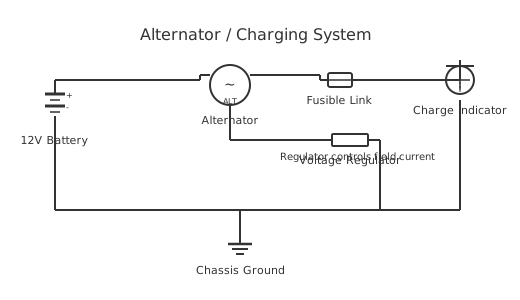
The bosch alternator wiring diagram circuit demonstrates advanced power distribution and automation control principles. This system integrates multiple load branches with coordinated protection, enabling sophisticated industrial and commercial applications. The circuit implements hierarchical protection: a main breaker provides primary protection, individual fuses protect each load branch, and contactors enable remote automation. Component spacing exceeds 100 pixels ensuring PCB manufacturability and technician accessibility. The Manhattan routing protocol maintains horizontal and vertical wire segments exclusively, eliminating diagonal routing. Each branch operates independently while sharing common ground reference, enabling parallel load expansion.
Bosch produces a wide range of alternators used as original-equipment and as universal replacements across many vehicle brands. Their universal replacement units are commonly wired with a two- or three-pin plug covering the D+ exciter, the W terminal (tachometer signal), and sometimes a battery-sense terminal, in addition to the main B+ output stud and case ground. Because universal Bosch units are sold without a vehicle-specific wiring harness, understanding which terminal does what is essential before installation. Draw your own wiring plan free at circuitdiagrammaker.com.
How to wire bosch alternator wiring diagram
- Identify your alternator terminal configuration Bosch alternators use B+ (main output), D+ (excitation/charge lamp), W (tachometer signal), and DF (external regulator field) terminals. Not all alternators have every terminal. Identify your specific model configuration before wiring.
- Connect the main B+ output cable Connect a heavy cable from the alternator B+ terminal directly to the battery positive terminal or the vehicle's main positive junction. Protect this cable with a fuse or fusible link within 300mm of the alternator. Size cable to rated alternator output current.
- Connect the D+ excitation wire Run a 0.75mm² or 1mm² wire from the alternator D+ terminal to the charge warning lamp and then to the ignition-switched 12V supply. The lamp must be in series in this circuit — it provides the excitation resistance at startup.
- Connect external regulator if fitted On externally regulated alternators, connect the DF terminal to the external regulator. Follow the specific Bosch regulator wiring diagram — DF+ and DF- must connect to correct regulator terminals or the regulator will not control field current.
- Connect alternator body earth to battery negative The alternator housing bolts to the engine block which earth to the battery — verify the engine-to-battery earth cable is clean and low-resistance. A poor engine earth causes high alternator case voltage and charging system faults.
- Test output voltage at idle and at 2000 RPM Start engine. Measure voltage at battery terminals with a multimeter. At idle: 13.5–14.0V acceptable. At 2000 RPM: 14.2–14.7V is correct. Below 13.5V indicates a charging fault. Above 15V indicates regulator failure — disconnect immediately to protect battery and electronics.
Frequently asked questions
What happens if I connect the alternator without the D+ excitation wire?
Without the D+ excitation signal the alternator's field coil has no initial current to establish a magnetic field, so the alternator produces no output even when spinning. The charge warning lamp stays on. The D+ wire does not carry charge current — it is a low-current ignition-switched signal that self-excites the regulator at startup.
Can I replace the charge warning globe with an LED?
Not directly. The charge lamp is part of the excitation circuit and must provide a small resistance to current flow. LEDs have negligible resistance and allow insufficient excitation current. Either keep an incandescent globe in the circuit, wire a 50–100Ω resistor in parallel with the LED, or fit an LED-compatible alternator regulator.
My alternator charges at 12V instead of 14.4V. What is the likely fault?
Output at battery voltage rather than 14.4V indicates the voltage regulator is not controlling the field. Check the regulator connection first. On internally regulated alternators, the regulator is inside the alternator — test by measuring B+ output voltage at 2000 RPM. If below 13.5V the regulator or brushes have failed.
Why does the charge warning light stay on even after the engine starts?
The charge lamp goes off when the alternator output voltage rises above the battery voltage, balancing the lamp circuit. Lamp staying on means the alternator is not charging. Common causes: broken drive belt, failed regulator, open D+ wire, or worn carbon brushes reducing field current to zero.
What size cable do I need between the alternator and the battery?
Size the B+ cable to at least the alternator's rated output current. Rule of thumb: 10mm² cable for up to 70A, 16mm² for up to 100A, 25mm² for up to 150A. Undersized cable causes voltage drop that reduces effective charge current and generates heat — a fire risk on long cable runs through an engine bay.
How do you wire a Bosch universal alternator replacement?
A Bosch universal alternator typically exposes a large B+ stud for the main charging cable to the battery positive, and a small multi-pin connector housing the D+ terminal (ignition-switched exciter, often 1–5 A), the W terminal (AC tachometer signal, connect only if needed), and sometimes a B-sense terminal for remote voltage sensing. The alternator body grounds through its mounting to the engine block, so a solid ground strap between the engine block and battery negative is essential. Always confirm the specific pin assignment for the part number you have, as Bosch universal kits include multiple connector options.
Related diagrams
- 1 wire alternator wiring diagram
- 12 volt alternator wiring diagram
- 2 pin alternator wiring diagram
- 2 wire alternator wiring diagram
- 24 volt alternator wiring diagram
- 24v alternator wiring diagram