Bosch Relay Wiring: 5-Pin and 7-Pin DIN 72552 Terminal Diagram Explained
This is a free printable bosch relay diagram: download the diagram as SVG or open it and print to paper or PDF.
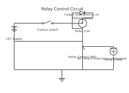
Understand how to wire the industry-standard Bosch-pattern ISO relay using DIN 72552 terminal numbering, including pin 30, 85, 86, 87, and 87a functions for automotive and 12V applications.
The term 'Bosch relay' refers generically to an ISO-standard miniature relay design that originated with Bosch and became so universally adopted that it is now the de facto relay form factor in automotive, marine, caravan, and 12 V power applications worldwide. The relay is defined by DIN 72552, the German standard for automotive electrical terminal numbering, which assigns specific functional numbers to each terminal — numbers that are consistent across all manufacturers producing this relay format.
The standard 5-pin Bosch-pattern relay uses the following terminal designations:
Pin 30 — Common (battery positive supply to the relay contact). Pin 85 — Coil ground (negative side of the relay coil, connected to chassis earth). Pin 86 — Coil positive (positive side of the relay coil, switched by the control signal). Pin 87 — Normally Open (NO) contact output — connects to Pin 30 when the coil is energised. Pin 87a — Normally Closed (NC) contact output — connects to Pin 30 when the coil is de-energised.
A 4-pin version omits Pin 87a (NC contact), making it a single pole, single throw (SPST) device. The 5-pin version is SPDT (single pole, double throw).
The 7-pin relay adds a second switched circuit, providing an additional NO/NC contact set for applications requiring simultaneous control of two independent circuits from a single coil.
For automotive use, Pin 30 connects directly to battery positive (typically via a fused supply), Pin 87 feeds the controlled load, and Pin 86 receives the switched control signal — for example, from an ECU output, a toggle switch, or a timer module. Pin 85 connects to chassis ground. This arrangement means the heavy load current flows through Pins 30 and 87 only when the relay is energised, allowing a low-current control signal at Pin 86 to switch high-current loads safely.
A flyback suppression diode (e.g. 1N4007) connected between Pins 85 and 86 (cathode to Pin 86) protects electronic control circuits from inductive kickback on coil de-energisation. Many modern relay sockets include this diode internally; check before adding an external one.
The Bosch-style 5-pin (SPDT) and 4-pin (SPST) automotive relays are among the most widely used in vehicle electrical work globally. Their standardised pin numbers — 30 (battery in), 85 and 86 (coil), 87 (normally-open output), and 87a (normally-closed output on 5-pin versions) — make wiring consistent across horn, lighting, and accessory applications. Understanding how to wire both the coil control side and the load side is essential for any automotive relay installation. Diagram your relay circuit for free at circuitdiagrammaker.com.
How to wire bosch relay diagram
- Identify the relay and socket pinout Locate the pin numbers moulded into the relay body or printed on the relay socket. Confirm Pins 30, 85, 86, 87, and 87a (5-pin) or 30, 85, 86, 87 (4-pin). The physical orientation of the pins follows the Bosch-standard blade layout — the pin positions are standardised so relays from different manufacturers are interchangeable in the same socket.
- Connect Pin 30 to the fused battery positive supply Run a cable from the battery positive terminal through an appropriately rated in-line fuse to Pin 30. Fuse this cable as close to the battery as possible (within 300 mm). The fuse rating should be based on the load current connected to Pin 87, not the battery cable capacity.
- Connect Pin 85 to chassis earth Connect Pin 85 to a clean, paint-free chassis earth point using a short cable. A poor earth connection at Pin 85 is a common cause of relay malfunction and intermittent operation. Use a stainless or brass ring terminal with the chassis bolt cleaned to bare metal.
- Connect Pin 86 to the control signal Connect Pin 86 to the switched positive control source — a switch, an ECU output, a timer, or another relay contact. This is the low-current control input that energises the coil. The coil draws approximately 150–200 mA at 12 V — within the range of most switches and ECU outputs.
- Connect Pin 87 to the load positive Connect Pin 87 to the positive input of the load (fan, horn, lights, pump, etc.). The load return connects to chassis earth independently. When the coil is energised, current flows from Pin 30 through the relay contact to Pin 87 and the load.
- Install flyback protection if needed If the control circuit (Pin 86) is driven by an electronic device, connect a 1N4007 diode between Pins 85 and 86 with the cathode (banded end) at Pin 86 (the positive control side). Check whether the relay socket already includes an internal diode before adding an external one.
- Test relay operation Apply control voltage to Pin 86 and confirm the relay clicks and the load operates. Remove control voltage and verify the load de-activates. Measure voltage drop across Pins 30 to 87 under load (should be less than 0.3 V for a healthy contact). Check all connections for heat after a few minutes of operation.
Specifications
| Terminal numbering standard | DIN 72552 (automotive terminal designation) |
|---|---|
| Pin 30 | Common — battery positive supply to contact |
| Pin 85 | Coil negative — chassis earth |
| Pin 86 | Coil positive — control signal input |
| Pin 87 | Normally Open output — active when coil energised |
| Pin 87a | Normally Closed output — active when coil de-energised (5-pin only) |
| Coil voltage (standard automotive) | 12 V DC nominal (operate range approximately 7–15 V) |
| Typical coil current at 12 V | Approximately 150–200 mA (verify relay datasheet) |
Safety warnings
- Always fuse the supply to Pin 30 as close to the battery as possible. An unfused wire between battery and relay is a fire hazard in the event of a short circuit anywhere in the load wiring.
- Disconnect the vehicle battery before performing any relay wiring modifications. Automotive battery systems can deliver thousands of amps into a short circuit — sufficient to weld wiring, destroy connectors, and start fires.
- Ensure all connections are clean and tight. Resistance at a poor automotive connection generates heat proportional to current squared. A 30 A load through a corroded spade terminal generates significant heat that can melt insulation and cause fire.
- Never route unfused cable through vehicle bodywork. If the cable is chafed by a sharp edge and shorts to body earth, the resulting current flow is limited only by cable resistance, generating enough heat to ignite wiring harnesses.
- Check the relay and socket contact rating before using it for high-current loads. A relay rated 30 A at 14 V DC on resistive loads may be significantly derated for motor or inductive loads such as electric fans or compressors.
Tools needed
- Digital multimeter (voltage, continuity, current)
- Crimping tool (for automotive spade and ring terminals)
- Wire strippers
- Heat gun (for heat shrink tubing)
- Fuse puller
- Screwdrivers (flat and Phillips)
- Test light or voltmeter probe
Common mistakes
- Connecting Pin 87a (NC contact) instead of Pin 87 (NO contact) as the load output, resulting in the load being on when the relay is off and off when it is on — exactly backwards.
- Omitting the in-line fuse on the Pin 30 supply cable, leaving a direct unfused connection from battery to relay that is a fire hazard in the event of a downstream short.
- Using a poor chassis earth at Pin 85 — corroded, painted, or high-resistance earth points cause voltage drop that prevents reliable coil pull-in, resulting in intermittent relay operation.
- Using undersized cable for the load circuit (Pins 30 and 87), causing voltage drop, heat buildup, and eventual insulation failure.
- Adding an external flyback diode to a relay socket that already contains one internally, causing the internal and external diodes to fight each other and potentially short the control circuit.
- Exceeding the relay contact rating by connecting a higher-current load than the relay is rated for, causing contact welding and load stuck-on faults.
Troubleshooting
- Relay clicks but load does not operate
- Cause: Load circuit fuse blown, poor connection at Pin 87 or load earth, or load device failed. Fix: Measure voltage at Pin 87 with relay energised — should be within 0.3 V of battery voltage. Check load fuse. Measure voltage at load positive terminal and load earth to confirm supply is reaching the load.
- Relay does not click when control voltage is applied
- Cause: Insufficient voltage at Pin 86, poor earth at Pin 85, faulty relay coil, or control signal source cannot supply the coil current. Fix: Measure voltage across Pins 86 and 85 — should be within 10% of rated coil voltage (e.g. 10.8–14 V for a 12 V relay). If voltage is correct and relay still does not click, replace relay. If voltage is absent or low, trace the control circuit for supply or earth faults.
- Relay operates intermittently, especially when hot
- Cause: Poor Pin 85 earth connection, corroded relay socket contacts, or coil voltage marginally below drop-out voltage due to supply sag under load. Fix: Clean relay socket contacts with electrical contact cleaner. Re-examine and re-make the Pin 85 earth connection. Measure battery voltage under full load to check for excessive supply sag. Consider upgrading supply cable if voltage drop is excessive.
Frequently asked questions
What do the numbers on a Bosch relay mean?
The numbers are DIN 72552 automotive terminal designations. Pin 30 is the main power input (battery positive via fuse). Pin 85 is coil negative (earth). Pin 86 is coil positive (control signal). Pin 87 is the normally open (NO) output — energised state. Pin 87a is the normally closed (NC) output — de-energised state. These numbers are standardised across all manufacturers making this relay format.
Which pins are interchangeable on a Bosch relay?
Pins 85 and 86 (the coil terminals) are electrically interchangeable for DC relays because the coil has no polarity. However, the DIN 72552 convention is 85 to ground and 86 to the switched positive, and this convention should be followed for consistency and for correct orientation of any internal flyback diode. Pins 30, 87, and 87a are not interchangeable — they are distinct contact terminals.
What is Pin 87a used for in automotive circuits?
Pin 87a (normally closed) is the contact that is active when the relay coil is de-energised. It is used when you want a circuit to be ON by default and switch OFF when the relay energises. Common automotive examples: activating a warning buzzer when a fan relay has not pulled in, or providing a fail-safe output that defaults to a safe state on power loss.
Do I need a flyback diode with a Bosch-pattern relay?
Yes, if the relay coil is switched by a transistor, ECU output, or relay module. The inductive kickback on de-energisation can damage electronic outputs. Fit a 1N4007 between Pins 85 and 86, cathode (banded end) to Pin 86. Many quality relay sockets have this diode built in — check the socket documentation before adding an external one to avoid forward-biasing the internal diode.
What is the difference between a 4-pin and 5-pin Bosch relay?
A 4-pin relay has Pins 30, 85, 86, and 87 — it is a single pole, single throw (SPST) device with only the normally open contact. A 5-pin relay adds Pin 87a (normally closed contact), making it single pole, double throw (SPDT). The 4-pin version is cheaper and sufficient for most simple switching applications; the 5-pin is needed when you require both NO and NC outputs.
How do you wire a Bosch relay for a horn?
Use a standard Bosch 4-pin (SPST) relay. Connect pin 30 to a fused battery-positive wire (typically through a 15–20 A fuse). Connect pin 87 to the horn positive terminal. Connect pin 86 to the horn button signal wire (the existing horn trigger from the steering column), and pin 85 to chassis ground. When the horn button is pressed, it sends 12 V to pin 86, energising the coil; the relay closes, sending full battery current through pin 30 to pin 87 and the horn.
How do you wire a Bosch relay for headlights?
For a headlight relay upgrade, connect pin 30 to a fused battery-direct wire sized for the lamp current (typically 20–30 A for a pair of halogen headlights). Connect pin 87 to the headlight positive wire(s). Run pin 86 to the original headlight switch output (the existing low-current headlight wire now acts only as a trigger), and connect pin 85 to chassis ground. This removes the full lamp current from the factory headlight switch, reducing voltage drop and extending switch life.
Related diagrams
- 11 pin relay wiring diagram
- 12 v relay diagram
- 12 volt relay wiring diagram
- 12v 5 pin relay wiring diagram
- 12v latching relay wiring diagram
- 12v relay module circuit diagram