Boss Plow Wiring Diagram
This is a free printable boss plow wiring diagram: download the diagram as SVG or open it and print to paper or PDF.
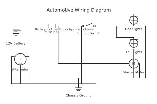
Understand how to read and troubleshoot a snowplow hydraulic control and solenoid wiring diagram, covering the control module, solenoid valve circuit topology, and power harness used in typical vehicle-mounted plows.
A vehicle-mounted snowplow electrical system integrates the vehicle's 12V DC battery with a hydraulic power unit, solenoid valve block, control module, and operator control device (joystick or handheld controller). The wiring topology is broadly consistent across most commercial snowplow systems, regardless of brand, because the underlying functions — pump motor control, solenoid valve selection, and ground switching — follow established automotive hydraulic principles.
The power circuit is the backbone of the plow electrical system. A heavy-gauge cable (typically 6 AWG or larger) connects the plow's power harness directly to the vehicle battery positive, protected by a high-current fusible link or circuit breaker rated for the hydraulic pump motor's stall current. A corresponding heavy earth cable runs from the plow frame or hydraulic unit to a clean chassis ground point. This direct-to-battery wiring is essential — the hydraulic pump motor draws 150–250 A at stall and requires a low-resistance supply path that the vehicle's existing wiring cannot provide.
The control harness connects the in-cab controller to the solenoid valve block and control module on the plow. Each solenoid valve in the hydraulic block controls a specific function: left angle, right angle, raise, lower, and in more complex systems, independent wing or blade functions. The control module receives input from the operator's controller and outputs ground-switching or supply-switching signals to the appropriate solenoid coil, causing the corresponding valve to open and direct hydraulic flow.
Solenoid coils in a snowplow system are typically 12V DC, single-acting (spring return). The control module switches the earth side of the solenoid coil in most designs — the solenoid coil positive is permanently connected to an ignition-switched supply, and the module provides the switched ground path. This minimises the current the control module itself carries on the signal lines.
The manufacturer's OEM wiring diagram for the specific plow and vehicle is the only authoritative reference for pinouts, harness connector details, and wiring colours. No generic diagram can substitute for the model-specific documentation. Always obtain the correct service wiring diagram from the manufacturer before attempting electrical diagnosis or repair.
How to wire boss plow wiring diagram
- Obtain the correct OEM wiring diagram for the specific plow and vehicle Before any electrical work on a snowplow system, obtain the manufacturer's service wiring diagram for the exact plow model, year, and the specific vehicle it is installed on. The vehicle harness connection points and plug types differ between truck makes and models. Download the documentation from the plow manufacturer's website or obtain it from an authorised dealer.
- Identify the three main circuit sections All snowplow electrical systems have three distinct sections: the power circuit (direct to battery, supplies pump motor), the solenoid valve circuit (switches individual hydraulic valves), and the control circuit (connects in-cab controller to the control module). Understanding which section a fault is in is the first step in any diagnosis.
- Inspect the power harness and connections Check the heavy-gauge battery supply cable for damage, corrosion at terminals, and security at the battery and at the plow unit. Inspect the fusible link or main circuit breaker — a blown fusible link is a common and often overlooked cause of complete plow power loss. Check the chassis earth connection for corrosion and security.
- Test pump motor operation independently With appropriate precautions, apply 12V directly from a known-good supply to the pump motor positive and negative terminals to verify the motor operates independently of the control system. If the motor runs directly but not from the system, the fault is in the relay or control circuit, not the motor. If it does not run directly, the motor or its direct wiring is at fault.
- Test individual solenoid valve coils Measure the resistance of each solenoid coil using a multimeter in resistance mode — a typical 12V solenoid coil reads 5–30 Ω. An open-circuit reading (OL/infinite) indicates a failed coil. A near-zero reading indicates a shorted coil. Test each solenoid in turn. Compare readings to the specification in the service documentation.
- Check the control harness connector for corrosion and damage The vehicle-to-plow connection point is exposed to salt, water, and mechanical stress every time the plow is attached or detached. Inspect the multi-pin connector for corroded or pushed-back pins, broken locking tabs, and damaged wires near the connector body. Clean with electrical contact cleaner and apply dielectric grease to prevent recurrence.
- Verify earth paths throughout the system Many intermittent plow electrical faults trace to poor earth connections — at the plow frame ground cable, at the solenoid valve body mounting, or at the control module mounting. With the system powered, measure the voltage drop across each earth path under load. More than 0.5V drop across an earth connection indicates a high-resistance joint that needs cleaning and tightening.
Specifications
| System voltage | 12V DC (vehicle electrical system) |
|---|---|
| Pump motor current draw (typical, running) | 80–150 A depending on hydraulic load and motor size |
| Pump motor stall current (typical) | 200–400 A — fusible link must be rated accordingly |
| Solenoid valve coil voltage | 12V DC |
| Solenoid coil resistance (typical) | 5–30 Ω — verify from OEM service documentation for specific model |
| Main supply cable minimum gauge | 6 AWG (typical minimum); 4 AWG or larger for installations over 3 m from battery |
| Control circuit voltage (typical) | 12V DC (supply from battery via ignition-switched relay or directly) |
| OEM wiring documentation source | Manufacturer's service manual for specific plow model and year — no generic pinout is applicable |
Safety warnings
- Always disconnect the vehicle battery negative terminal before working on the plow wiring harness or replacing electrical components. The main power supply cable is connected directly to the battery and is live at all times — there is no ignition switch in the main power circuit. Accidental short-circuit of the supply cable can generate very high fault currents, causing fire, severe burns, or explosion of the battery.
- Never bypass or upsize the fusible link or circuit breaker in the main power circuit. These devices protect the wiring from fire in the event of a short circuit. Bypassing them removes the only protection against a catastrophic wiring fire in the power cable.
- Plow hydraulic cylinders can move suddenly when the control system is powered. Keep hands and body clear of the plow blade, cutting edge, lift frame, and angle cylinders whenever the electrical system is powered. Unexpected activation due to a wiring fault can cause crushing injury.
- The hydraulic fluid circuit and its components operate at high pressure. Do not loosen hydraulic fittings or hoses to diagnose electrical problems — hydraulic leaks under pressure can inject fluid into tissue (injection injuries) or cause fire if fluid contacts hot exhaust components.
- This document describes general snowplow electrical circuit topology for educational reference only. No specific product pinouts, connector details, or model-specific wiring information is provided or implied. Always use the manufacturer's OEM service wiring diagram for the specific plow and vehicle before performing any electrical work.
Tools needed
- Multimeter with DC voltage, resistance, and continuity functions
- Clamp ammeter (to measure pump motor current draw during operation)
- Battery load tester (to verify battery and charging system capacity)
- Electrical contact cleaner and dielectric grease (for connector maintenance)
- Wire brush and terminal cleaning tools (for corrosion removal)
- Screwdrivers and ratchet/socket set (for harness mounting and connector access)
- Wiring diagram for the specific plow model and vehicle (from OEM service documentation)
Common mistakes
- Neglecting the main earth cable: A loose, corroded, or undersized earth cable is the most common cause of poor plow performance — slow hydraulic operation, erratic function response, and control module faults. The earth path must be as short and low-resistance as the supply cable.
- Replacing the pump motor before testing the relay: A pump that fails to run is often caused by a failed pump relay or its control circuit, not the motor itself. Test the relay and verify battery voltage at the motor terminals before condemning an expensive pump motor.
- Using undersized cable for a harness repair: Replacing a section of the main power harness with a smaller-gauge wire causes voltage drop, heat, and premature failure. The entire power harness run must maintain the gauge specified in the OEM documentation.
- Ignoring intermittent connector corrosion at the vehicle-plow junction: This multi-pin connector is subjected to salt, water, and mechanical cycling every time the plow is attached and removed. Corroded pins cause intermittent function loss that appears as a control system or solenoid fault. Clean and protect connectors at the start of every plowing season.
- Diagnosing the control module before verifying the supply voltage: A control module that appears faulty — not responding to controller inputs, erratic function — may simply be seeing insufficient supply voltage due to a high-resistance connection or a weak battery. Verify that the module is receiving correct supply voltage before replacing it.
Troubleshooting
- Plow has no power — no pump operation and no controller response
- Cause: Blown fusible link in main power cable, failed main pump relay, poor battery connection, or open-circuit in main earth cable Fix: Check the fusible link at the battery — a blown fusible link is a common and visible failure (the link melts and separates). Check battery voltage under load. Verify voltage at the pump motor relay input terminal. Check earth cable resistance from plow frame to chassis ground. Work systematically from the battery outward.
- One plow function does not operate (e.g., left angle only)
- Cause: Failed solenoid coil on that function's valve, open-circuit wiring to that solenoid, or failed output on the control module for that function Fix: Measure solenoid coil resistance with a multimeter — an open circuit or dramatically out-of-specification reading confirms a failed coil. Check wiring continuity from the control module output to the solenoid coil. If wiring and solenoid are good, verify the control module is outputting the correct signal when that function is commanded.
- Plow operates slowly or weakly on all functions
- Cause: High resistance in the main power or earth circuit causing voltage drop, weak or discharged battery, or alternator not keeping up with hydraulic pump demand Fix: Measure battery voltage at the pump motor terminals under load — should be close to 12V. Large voltage drop indicates resistance in the supply or earth path. Inspect all connections in the main power circuit for corrosion and tightness. Load-test the battery. Check alternator output voltage with pump running.
Frequently asked questions
Why does a snowplow connect its power directly to the vehicle battery?
The hydraulic pump motor draws 150–250 A or more at stall — far more than the vehicle's accessory wiring can supply without severe voltage drop. A direct battery connection with appropriately sized cable minimises resistance in the supply path, ensures adequate pump performance, and prevents overloading the vehicle's factory wiring. A fusible link or high-current circuit breaker in this direct supply protects the cable from short-circuit damage.
What does each solenoid valve do in a plow hydraulic circuit?
Each solenoid valve directs hydraulic fluid to a specific cylinder or allows it to return to the reservoir. In a typical straight-blade plow, individual valves control: raise (lift cylinder extend), lower (lift cylinder retract or float), left angle (angle cylinder for left movement), and right angle (angle cylinder for right movement). The control module activates the correct valve or valves in combination for each operator command.
How do I identify a failed solenoid valve in a plow electrical circuit?
With the plow powered, measure DC voltage at both terminals of each solenoid coil when it should be activated. Both terminals should read approximately 12V when the coil is inactive (switched ground open). When activated, one terminal should drop to near 0V (the switched ground side closes). If voltage does not change when the function is commanded, the control module output or the wiring to that solenoid is the fault. If voltage changes correctly but the function does not occur, the solenoid coil or valve mechanism is at fault.
Can I use a generic wiring diagram to wire a replacement plow harness?
For the general circuit topology — power, pump, solenoid switching, control module — a generic reference diagram shows how the circuit is constructed and how to trace faults. However, specific connector pinouts, wire colours, harness connector part numbers, and control module interface requirements vary between manufacturers and even between models and years from the same manufacturer. Always use the OEM wiring diagram for the specific plow model when making connections or replacing harness components.
What is a fusible link and why is it used in plow wiring?
A fusible link is a short section of wire with a significantly smaller gauge than the cable it protects, or a dedicated fusible element, installed in the battery supply cable. It melts and opens the circuit under a sustained short-circuit current before the main cable or vehicle wiring is damaged. Fusible links handle the very high fault currents possible in direct battery connections where a standard blade fuse would need to be impractically large. Some newer systems use a resettable circuit breaker instead.
Related diagrams
- boss plow solenoid wiring diagram
- boss plow wiring harness
- boss 13 pin wiring harness diagram
- boss audio system wiring diagram
- boss be7acp wiring diagram
- boss radio wiring diagram