dol connection diagram
This is a free printable dol connection diagram: download the diagram as SVG or open it and print to paper or PDF.
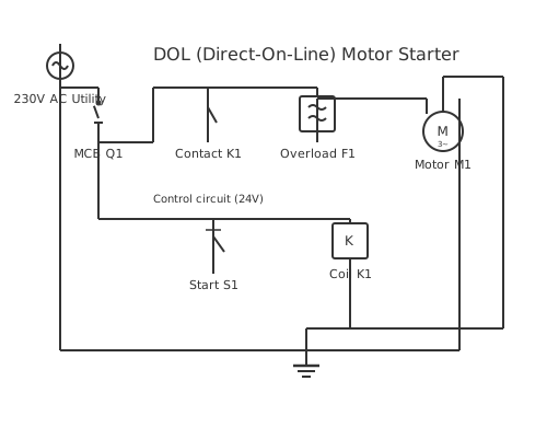
A DOL connection diagram provides detailed wiring instructions for installing direct-on-line motor starters, showing phase connections, control circuits, and protection device wiring sequences. The diagram serves as a construction guide for electricians implementing DOL control systems in industrial settings. Understanding DOL connection diagrams ensures proper motor operation, compliance with electrical codes, and safe working conditions. The diagram illustrates three-phase power distribution where each phase supplies a contactor pole, with simultaneous contacts ensuring balanced three-phase motor supply. Control circuits typically operate at lower voltage (120V) derived from the three-phase supply through control transformers. The diagram shows how contactor interlocks prevent accidental simultaneous operation of conflicting control signals. Proper phase sequencing ensures correct motor rotation direction preventing mechanical damage to driven machinery.
How to wire dol connection diagram
- Print or sketch the connection diagram Before touching any wires, have the connection diagram on paper or tablet in front of you. Mark off each connection as you complete it. This prevents missed connections and speeds up commissioning checks.
- Isolate and lock out the supply Switch off and lock out the upstream isolator. Attach a personal lock and test with a multimeter that all three phases and neutral are dead before opening the enclosure or touching terminals.
- Mount components on DIN rail Fix the MCB, contactor, and overload relay in the order shown on the connection diagram, left to right. Leave at least 10 mm between components for air circulation and finger access to terminal screws.
- Run main power cables Feed supply cables L1, L2, L3 into the enclosure and terminate on the contactor input terminals. Use the cable cross-section specified on the diagram. Do not over-strip insulation — 8 mm exposed conductor is sufficient for most terminals.
- Connect overload relay to motor cable Run the motor cable from overload relay output terminals to the motor terminal box. Confirm T1 to U, T2 to V, T3 to W. Use a cable gland at the motor entry to prevent vibration damaging the termination.
- Wire the control circuit Following the control wiring section of the connection diagram, wire stop button, start button, hold-in contact, and coil in sequence. Use a different wire colour from the main circuit to distinguish control conductors instantly during fault-finding.
- Terminate the earth conductors Connect the supply earth to the enclosure earth bar. Run a separate earth conductor from the earth bar to the motor frame earth terminal. Verify continuity end-to-end with a multimeter before energising.
- Commission and record Energise, test start and stop, check rotation, measure running current on all three phases. Record the readings on the connection diagram and file it permanently in the panel door or plant records folder.
Frequently asked questions
What is the difference between a DOL circuit diagram and a DOL connection diagram?
A circuit diagram shows the electrical logic using standard schematic symbols. A connection diagram shows the physical wiring between actual terminals and components. Electricians use the connection diagram on the job; engineers use the circuit diagram for design and fault analysis.
How do I know which terminal on the contactor goes to the motor?
On a standard three-phase contactor, the output terminals are labelled T1, T2, and T3. These connect to the overload relay input. The overload relay output terminals then connect to motor terminals U, V, and W. Always verify against the specific contactor manufacturer's terminal diagram.
Does the earth conductor connect to the contactor in a DOL connection?
No. The earth conductor bypasses the contactor entirely and connects directly from the supply earth bar to the motor frame. The contactor switches only the live phase conductors. Breaking earth through a switching device is not permitted under South African wiring regulations.
What colour coding applies to DOL wiring in South Africa?
Per SANS 10142-1, three-phase conductors are red, white, and blue for phases L1, L2, and L3. Neutral is black. Earth is green-and-yellow. Control wiring is typically grey or orange. Consistent colour coding makes fault-finding on DOL panels significantly faster.
Can I use the connection diagram to add a second start button at a remote location?
Yes. Wire the remote start button in parallel with the existing start button, and the remote stop button in series with the existing stop button. The hold-in contact across the local start button covers both positions. Mark the remote station clearly on your as-built connection diagram.
Related diagrams
- 3 phase dol starter wiring diagram
- dol circuit diagram
- dol control diagram
- dol power diagram
- dol starter circuit diagram
- dol starter control circuit