Ecm motor wiring diagram: Complete Wiring Reference
This is a free printable ecm motor wiring diagram: download the diagram as SVG or open it and print to paper or PDF.
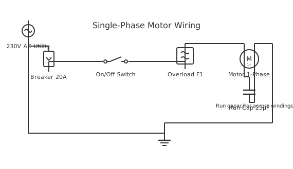
Understanding ecm motor wiring diagram is essential for proper electrical system installation and operation. This guide provides detailed instructions for safe wiring.
The ecm motor wiring diagram system requires proper component selection, appropriate wire gauging, and correct connection methods. Installation follows standard electrical practices: de-energize before work, use appropriate protection devices, ensure reliable ground connections, and test all circuits before operation. Proper wire gauge selection prevents voltage drop and overheating. Protection devices must match wire ampacity, not load requirements. Grounding provides safe fault current paths. Common failures result from inadequate protection, poor connections, or undersized conductors. Professional installation includes measuring run distances, selecting color-coded wires, and verifying operation under full load. Component quality matters—cheap connectors cause intermittent failures. Regular maintenance and visual inspection confirm continued safe operation. Thermal management through proper ventilation prevents overheating and extends equipment lifespan.
ECM (Electronically Commutated Motor) wiring diagrams differ from conventional PSC motor diagrams because the motor contains an integrated variable-speed controller that communicates with the HVAC control board via a low-voltage signal harness alongside the high-voltage power leads. Popular variants include the X13, Genteq, and GE ECM 2.3. Each brand uses a specific multi-pin connector for the control interface, so matching the correct diagram to your motor model is essential before any wiring work.
How to wire ecm motor wiring diagram
- Review the complete wiring diagram and gather all required components matching your application and local codes.
- Prepare wiring: measure lengths, strip insulation carefully, and prepare terminal connections with appropriate crimpers.
- Install components securely with proper orientation and adequate ventilation clearance.
- Make connections following the diagram exactly, using color-coded wires and rated terminals.
- Test and verify: confirm continuity, polarity, and voltage; operate under load and verify all functions work.
Frequently asked questions
What are the key safety rules for electrical installation?
Always de-energize circuits before working. Use lockout/tagout procedures. Wear insulated tools and PPE. Test for voltage presence before touching. Follow manufacturer specs and local codes. Never work alone on high-voltage systems.
How do I determine proper wire gauge?
Wire gauge depends on circuit current and run length. Higher current requires thicker wire. Use ampacity tables from NEC codes. For runs over 100 feet, increase gauge by one or two steps to compensate for voltage drop.
What fuse or breaker rating should I use?
Breaker rating must match the circuit wire gauge, never the load. Undersized breakers cause nuisance trips; oversized creates fire hazards. Always follow application manual specifications exactly.
Why is grounding so critical?
Grounding provides safe return paths for fault currents, allowing protection devices to detect shorts quickly. It prevents dangerous voltages on exposed metal and reduces electrical noise. Never compromise grounding.
What tools do I need?
Wire strippers, crimpers, multimeter, screwdrivers, insulated pliers, and torque wrenches for high-current connections. Always use quality, insulated tools for safety.
How do I wire an X13 ECM motor?
The X13 ECM motor uses a 5-pin low-voltage control connector and a separate high-voltage power connector (typically L1, L2/Neutral, and Ground). The control connector carries 24 VAC common, 24 VAC hot, and tapped speed-select inputs (G, Y, W) from the thermostat signals via the furnace or air-handler control board. Speed is determined by which 24 V signal is active rather than by capacitor or tap selection. Always follow the specific OEM wiring diagram for the unit the X13 is fitted in, as connector pinouts can vary by motor revision.
What does a Genteq ECM motor wiring diagram look like?
A Genteq ECM motor (commonly a 2.3 or 5.0 series) wiring diagram shows two connectors: a high-voltage plug (line, neutral, earth) and a low-voltage 16-pin communication connector carrying 24 VAC power, common, and individual speed-select or communicating-protocol wires. The motor's integrated module receives thermostat call signals through the control board and adjusts blower speed accordingly. Never apply high voltage to the control pins; refer to the Genteq ECM installation guide or the equipment manufacturer's wiring diagram for the specific tap-to-CFM assignments.
How is the GE ECM 2.3 motor wired?
The GE ECM 2.3 motor uses the same two-connector approach as other Genteq/GE ECM motors: 120/240 VAC power to the power connector (L1, L2, Ground) and a 16-pin Molex-style control connector for 24 VAC and speed-select signals. The specific speed taps (typically four or five) correspond to airflow CFM values programmed for that equipment. The control board activates the appropriate tap wire when the thermostat calls for heating, cooling, or fan-only. Consult the OEM furnace or air-handler wiring diagram to correctly identify which terminal on the control board connects to each ECM speed tap.
Related diagrams
- 1 phase motor connection
- 115 230 volt motor wiring diagram
- 12 lead motor wiring
- 12 wire motor wiring diagram
- 120 240 volt motor wiring diagram
- 2 speed motor wiring diagram