electric heater wiring diagram
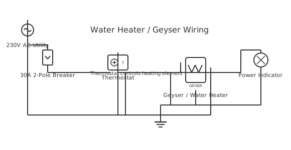
This is a free printable electric heater wiring diagram: download the diagram as SVG or open it and print to paper or PDF.
Diagram checks and scope
- Components
- 6
- Wired connections
- 11
- Automated check
- Automated pin, route, source, and topology checks passed; this is not a safety certification.
An electric heater wiring diagram illustrates the power distribution, control, and safety circuit configuration for electric space heaters, baseboard heaters, or resistance heating elements. The diagram shows 240V single-phase or 208V service fed through a dedicated circuit breaker to a thermostat that modulates power delivery to the heating element. Electric heaters convert 95%+ of electrical energy directly to heat through high-resistance wire or ceramic element, making them highly efficient but requiring substantial electrical capacity. The diagram identifies: main disconnect switch, circuit breaker sized for element current draw, thermostat switching contacts, and grounding conductor. Safety devices include high-limit thermostats that disconnect power if temperature exceeds safe limits (preventing fire risk), and ground-fault circuit interrupter (GFCI) protection in bath and wet locations. Modern electric heater diagrams show electronic controllers with setpoint display, timer functions, and remote wireless control capability. Understanding electric heater wiring enables safe installation, proper circuit capacity verification, and diagnosis of heating failures.
How to wire electric heater wiring diagram
- Confirm heater nameplate requirements Read the nameplate for wattage, supply voltage, and whether the heater requires a dedicated circuit or can be plug-connected. A 2 400 W heater on a 3-pin socket is at the upper limit of a 13 A fused plug — fit a 13 A fuse in the plug, not 5 A, to avoid nuisance blowing.
- Install a dedicated MCB if hardwiring For hardwired heaters, fit a dedicated MCB rated at 125% of the heater full-load current. In a distribution board, label it clearly. A hardwired heater without a clearly labelled dedicated MCB creates a dangerous situation if someone works on the board without checking for heater load.
- Run the supply cable Use cable rated for the heater current and ambient temperature of the route. Heater supply cables routed inside walls or under carpets must be sized conservatively — continuous high-current operation in an enclosed space generates heat that degrades cable insulation faster than intermittent loads.
- Wire the thermostat in series Connect the thermostat in series with the live supply conductor to the element. Most room thermostats break the live conductor only. For higher-powered heaters, use a thermostat-controlled relay or contactor if the thermostat is not rated for the full heater current — small thermostats typically switch maximum 10 A.
- Connect the overheat cutout Wire the overheat cutout in series with the thermostat and element. The cutout is usually already pre-wired inside the heater during manufacture — verify it is intact and correctly positioned against the element housing before connecting the supply.
- Earth the heater enclosure Connect the supply earth conductor to the heater body earth terminal. Verify earth continuity from the heater body to the distribution board earth with a multimeter. An unearthed metal heater casing will become live if an element develops an insulation fault — this is a lethal hazard.
- Test under load Restore power and operate the heater through a full cycle — verify the element heats, the thermostat shuts off at setpoint, and the heater restarts when temperature drops. Measure current with a clamp meter and compare to the nameplate rating. Significantly higher current indicates a winding fault; lower indicates an open element section.
Frequently asked questions
What size circuit breaker do I need for an electric heater?
Size the MCB at 125% of the heater's full-load current. A 2 400 W heater on 230 V draws approximately 10.4 A, requiring a 13 A or 16 A MCB. For permanently installed heaters, a dedicated circuit is required. Never share a heater circuit with other significant loads.
Do I need a thermostat in the wiring diagram for an electric heater?
For any permanent or semi-permanent installation, yes. A thermostat prevents the heater running continuously, controls comfort temperature, and extends element life by reducing thermal cycling. Wire the thermostat in series with the heater element supply — when the room reaches setpoint, the thermostat opens and cuts heater power.
Can I install an electric heater on a ring main circuit?
A heater below 3 000 W can technically be fed from a ring main via a switched fused connection unit (FCU) in the UK wiring system. In South African residential wiring under SANS 10142-1, permanently installed heaters above 1 000 W should ideally have a dedicated circuit. Consult a registered electrician for your specific installation.
What is the wiring difference between a radiant heater and a convector heater?
Electrically, both are simply resistance elements supplied with mains voltage. A radiant heater may use a quartz tube element with a visible glow; a convector uses a nichrome or similar element behind a grille. The wiring diagram for both is identical — supply, thermostat, overheat cutout, and element. Only the mechanical housing differs.
What does the overheat cutout do in a heater wiring diagram?
The overheat cutout (thermal cutout or thermal limiter) is a one-shot or resettable safety device that opens the heater circuit if the element temperature exceeds a safe limit. It triggers if airflow is blocked or if the heater is covered. A non-resettable cutout that keeps blowing means the heater has a blocked air path or a failed fan.
Sources and verification
Review status: Not independently reviewed. Automated topology checks confirm stored terminals and routes, not the correctness of manufacturer pin assignments, ratings, regional codes, or installation decisions. Verify those claims against the current primary documentation before use.
- IEC 61082-1:2014 — Rules for electrotechnical documents — International Electrotechnical Commission. Supports: General diagram, drawing, table, and reference-designation presentation conventions. Checked 2026-07-15.
Related diagrams
- 240v electric water heater wiring diagram
- electric water heater wiring diagram
- rheem electric water heater wiring diagram
- electric board connection diagram
- 220v hot water heater wiring diagram
- 240v heater wiring diagram