Motor Power and Control Integration
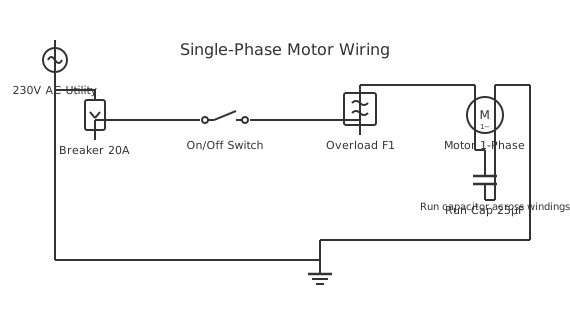
This is a free printable electric motor wiring diagram: download the diagram as SVG or open it and print to paper or PDF.
An electric motor wiring diagram integrates high-current power circuits with low-voltage control circuits for coordinated motor operation.
Diagram checks and scope
- Components
- 7
- Wired connections
- 8
- Automated check
- Automated pin, route, source, and topology checks passed; this is not a safety certification.
Electric motor circuits separate into two distinct subsystems: the power circuit delivering high current to motor windings, and the control circuit operating protective relays at lower voltage. The power circuit path flows from the breaker through a disconnect switch directly to the motor starter input terminals. The motor starter main contacts handle full load current, typically many hundreds of amperes for large motors. Thermal overload relays sense the average motor current and disconnect power if sustained overcurrent indicates overheating. The control circuit operates at 120V or 24V, isolated from power circuit by a control transformer. Start and stop pushbuttons control contactor coil energization through the control circuit. Indicator lights display motor running status and fault conditions. Permissive switches may prevent motor start unless certain conditions are met: door closed, pressure within limits, or equipment interlock satisfied. The circuit logic prevents simultaneous activation of conflicting outputs. Emergency stop circuits override normal logic and disconnect power immediately. All field wiring must be shielded to prevent noise coupling into the sensitive analog control circuits. Proper motor wiring enables safe, efficient operation and rapid troubleshooting of problems.
How to wire electric motor wiring diagram
- Obtain the motor specifications: horsepower, voltage, phase, and operating characteristics
- Design the control logic flowchart showing all interlocks and safety conditions
- Install the motor starter with contactor and overload relays rated for the motor
- Wire the control transformer, start/stop buttons, and indicator lights in the control circuit
- Route power cables to the motor using proper gauge and conduit protection
Frequently asked questions
Why separate power and control circuits?
Separation protects personnel and allows safe operation of pushbuttons while handling high currents.
What voltage should I use for motor control circuits?
120V is standard in North America for safety and compatibility with standard control components.
What is a holding contact in motor circuits?
A holding contact is an auxiliary contact that maintains contactor energization after the start button is released.
Why do motors need interlocks?
Interlocks prevent unsafe equipment operation, such as starting when maintenance doors are open.
Can I add remote control to an existing motor?
Yes, if the contactor coil is accessible, wireless remote receiver modules can control the existing circuit.
Sources and verification
Review status: Not independently reviewed. Automated topology checks confirm stored terminals and routes, not the correctness of manufacturer pin assignments, ratings, regional codes, or installation decisions. Verify those claims against the current primary documentation before use.
- IEC 61082-1:2014 — Rules for electrotechnical documents — International Electrotechnical Commission. Supports: General diagram, drawing, table, and reference-designation presentation conventions. Checked 2026-07-15.
Related diagrams
- 3 speed electric fan motor wiring diagram
- 6 wire electric motor wiring diagram
- electric motor parts diagram
- 4 wire stepper motor wiring diagram
- electric board connection diagram
- servo motor circuit diagram