micro usb wiring diagram
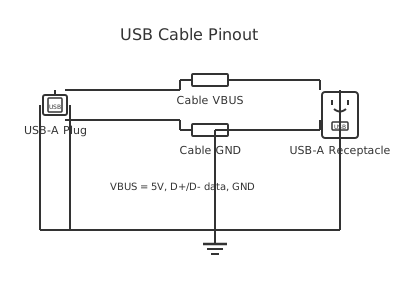
This is a free printable micro usb wiring diagram: download the diagram as SVG or open it and print to paper or PDF.
Diagram checks and scope
- Components
- 5
- Wired connections
- 9
- Automated check
- Automated pin, route, source, and topology checks passed; this is not a safety certification.
A micro USB wiring diagram details the internal connections and pin functions of the ubiquitous micro USB connector standard that powered mobile devices, tablets, and small electronics for over a decade. The micro USB Type-B connector contains five pins arranged in a specific pattern: Vbus (power +5V), Ground (GND), Data-, Data+, and ID. Understanding the pin assignments and function of each conductor is essential for repairing broken connectors, creating custom cables, or designing charging circuits. The Data+ and Data- pins implement a differential signaling protocol for USB communication, allowing both power delivery and data transfer through a single small connector. The ID pin ground detection enables automatic switching between host and device modes or charging modes. Despite micro USB's replacement by USB Type-C in newer devices, billions of micro USB powered devices remain in active use, making knowledge of this connector critical for technicians and DIY enthusiasts. Proper wiring prevents damage to devices, ensures fast charging, and enables reliable data synchronization. The small form factor requires careful soldering and strain relief to prevent connection failures from mechanical stress.
How to wire micro usb wiring diagram
- Obtain a micro USB Type-B connector and identify the five pins using the standard pinout diagram
- Prepare five wires of appropriate gauge: 20-24 AWG for data lines, 18-20 AWG for power lines, with different color insulation for easy identification
- Solder the wire from your cable to each micro USB pin, ensuring mechanical and electrical connection with sufficient solder coverage
- Apply heat shrink tubing over each individual wire joint and the entire connector assembly to prevent short circuits and provide strain relief
- Test continuity between cable wires and connector pins using a multimeter, verifying no shorts between adjacent pins exist
Frequently asked questions
What are the five pins on a micro USB connector?
Pin 1 (Vbus): +5V power supply. Pin 2 (Data-): Negative data line for USB communication. Pin 3 (Data+): Positive data line for USB communication. Pin 4 (ID): Ground detection pin for host/device mode identification. Pin 5 (Ground): Power and signal return connection.
Why do some micro USB cables charge slowly?
Slow charging typically results from: high-resistance connections due to corroded pins, undersized wire gauge causing voltage drop, poor solder joints increasing resistance, or the charger producing insufficient current. High-resistance connections reduce charging power and generate excessive heat in the connector.
Can I use a micro USB cable for data transfer and charging simultaneously?
Yes, a properly wired micro USB cable carries both power and data. However, many cheap cables omit the data pins to reduce cost and complexity. Check that Data+ and Data- pins have proper solder connections. Devices will charge through power-only cables but cannot sync or transfer data.
What happens if I connect Vbus and Ground directly together in a micro USB cable?
Connecting Vbus and Ground creates a dead short, instantly destroying the charger or power supply. This is a catastrophic failure that may also damage the powered device. Always verify wiring carefully before applying power. Use a multimeter to test continuity between correct pins.
Why does my phone not recognize this micro USB cable for data?
The cable likely has faulty or missing data pins. Verify Data+ (pin 3) and Data- (pin 2) have solid solder connections from the connector to the cable. Clean connector pins with isopropyl alcohol and a small brush if corroded. Test the cable with a multimeter to verify continuity on all five pins.
Sources and verification
Review status: Not independently reviewed. Automated topology checks confirm stored terminals and routes, not the correctness of manufacturer pin assignments, ratings, regional codes, or installation decisions. Verify those claims against the current primary documentation before use.
- IEC 61082-1:2014 — Rules for electrotechnical documents — International Electrotechnical Commission. Supports: General diagram, drawing, table, and reference-designation presentation conventions. Checked 2026-07-15.
- USB 2.0 Specification — USB Implementers Forum. Supports: USB 2.0 interface, cable, electrical, signal, protocol, and connector requirements. Checked 2026-07-15.
Related diagrams
- micro usb cable wiring diagram
- micro usb pinout diagram
- female usb pinout
- mini usb wiring diagram
- usb 2.0 wiring diagram
- usb a pinout diagram