rccb connection diagram
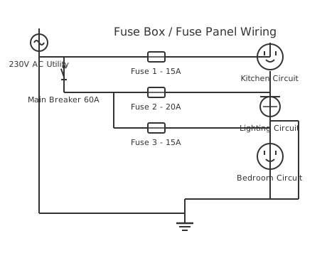
This is a free printable rccb connection diagram: download the diagram as SVG or open it and print to paper or PDF.
Diagram checks and scope
- Components
- 9
- Wired connections
- 11
- Automated check
- Automated pin, route, source, and topology checks passed; this is not a safety certification.
A Rccb Connection Diagram wiring diagram provides comprehensive guidance for electrical installation and troubleshooting in automotive and industrial applications. This specialized diagram illustrates the proper connections, wire gauges, component placement, and safety procedures required for correct system operation. Understanding this wiring is essential for technicians, electricians, and professionals working with electrical systems. The diagram shows all connections with color coding, amperage ratings, and grounding requirements to ensure safe and reliable operation. Proper installation following this diagram prevents electrical hazards, system failures, and compliance issues. The schematic includes detailed information about terminals, connections, and circuit protection measures. Professional implementation of this diagram ensures optimal system performance, equipment longevity, and electrical safety for all users and equipment.
How to wire rccb connection diagram
- Confirm RCCB rating matches the circuit load Select RCCB current rating at or above the circuit MCB rating. A 32A RCCB on a 40A MCB circuit means the MCB will not trip on overload before the RCCB sees fault current — incorrect sizing.
- Identify line and load terminals RCCB terminals are marked: supply side (LINE, N-in, L-in or top terminals) and load side (LOAD, N-out, L-out or bottom terminals). Connecting backwards — supply to load terminals — causes RCCB malfunction.
- Connect the line (supply) conductors to the top Per SANS 10142-1 convention, supply conductors enter from the top of the RCCB. Red or brown (live) to L-in terminal, blue or black (neutral) to N-in terminal.
- Connect load conductors from the bottom terminals Outgoing live exits from L-out, neutral from N-out. These feed the protected circuit MCBs or directly to socket outlets and fixed equipment in the circuit.
- Never connect neutral to earth on the load side A neutral-earth bond downstream of the RCCB causes permanent differential current and trips the device. The neutral-earth bond must exist only at the main earthing terminal, upstream of the RCCB.
- Test the RCCB using the test button monthly Press the TEST button with the circuit live. The RCCB must trip within 300ms for a 30mA device per IEC 61008. A device that does not trip on test is defective and must be replaced immediately.
- Label the RCCB with trip sensitivity and circuit served Mark 30mA (general use) or 10mA (medical/special locations) on the distribution board schedule. SANS 10142-1 requires a completed and legible DB schedule — an unmarked board is a compliance failure.
Frequently asked questions
What is an RCCB and what does it protect against?
A residual current circuit breaker (RCCB) detects earth leakage current caused by insulation faults or contact with live parts. It trips when the difference between current flowing out on the live and returning on the neutral exceeds the trip threshold — typically 30mA for personal protection.
What is the difference between a 10mA and 30mA RCCB?
A 10mA RCCB trips faster and at lower leakage current — it is used for added protection on circuits where the risk is higher, such as outdoor sockets or medical equipment locations. 30mA is the standard for general domestic and commercial circuits per SANS 10142-1.
Can an RCCB protect against overcurrent?
No. A standard RCCB only detects earth leakage — it does not protect against overloads or short circuits. You must have a circuit breaker (MCB or MCCB) in series with the RCCB to provide overcurrent protection, or use an RCBO which combines both functions.
How do I know if my RCCB has tripped rather than a circuit breaker?
An RCCB typically has a test button and a trip indicator that shows when it has tripped. The handle sits in a middle position between on and off when tripped. To reset, move the handle fully to the off position first, then switch back on.
How often should I test an RCCB?
Test using the test button monthly for domestic installations and every three months for commercial circuits. Press the test button — the RCCB must trip immediately. If it does not trip, the unit has failed and must be replaced before it will provide protection.
Sources and verification
Review status: Not independently reviewed. Automated topology checks confirm stored terminals and routes, not the correctness of manufacturer pin assignments, ratings, regional codes, or installation decisions. Verify those claims against the current primary documentation before use.
- IEC 61082-1:2014 — Rules for electrotechnical documents — International Electrotechnical Commission. Supports: General diagram, drawing, table, and reference-designation presentation conventions. Checked 2026-07-15.