Receptacle Wiring Diagram
This is a free printable receptacle wiring diagram: download the diagram as SVG or open it and print to paper or PDF.
Wire electrical receptacles correctly — covering standard single outlets, GFCI receptacles, switch-controlled outlets, and daisy-chain loop wiring — with correct terminal identification and safety requirements.
A receptacle (wall outlet or socket outlet) is the interface between the fixed electrical wiring of a building and portable equipment. Correct wiring of receptacles requires understanding terminal identification, protective earth connections, ground-fault protection, and the effect of downstream wiring on adjacent outlets in a circuit.
In North American wiring practice (NEC/NFPA 70), a duplex receptacle has three terminal types: the narrow blade slot (hot/active) terminal, which is brass-coloured and connects to the black insulated conductor; the wider blade slot (neutral) terminal, which is silver-coloured and connects to the white insulated conductor; and the U-shaped earth pin (ground) terminal, which is green-coloured and connects to the bare copper or green-insulated protective conductor. Connecting hot to neutral at the receptacle causes immediate fuse or breaker operation; connecting hot and neutral in reverse (reversed polarity) is a safety hazard where the outer shell of screw-cap lamp bases and some appliances becomes energised when switched off.
In IEC wiring practice (BS 7671 and IEC 60364-compatible countries), socket outlets use a different physical format but the same principle: a live (Line or L) terminal, a neutral (N) terminal, and a protective earth (PE or E) terminal. In the UK, the standard 13 A BS 1363 socket has the earth at the top (largest pin) and live/neutral at the bottom. Live connects to the right-hand lower terminal (looking at the face of the socket), and neutral to the left-hand lower terminal.
GFCI (ground-fault circuit interrupter) receptacles, called RCDs or RCCBs in IEC jurisdictions, contain an electronic sensing circuit that monitors the balance between line and neutral currents. If the difference exceeds approximately 4–6 mA (indicating current leaking to ground through a person or fault path), the GFCI trips within about 25 milliseconds. GFCI receptacles have LINE and LOAD terminal sets — the LINE terminals connect to the supply, and the LOAD terminals, if used, provide GFCI protection to all receptacles wired downstream from the LOAD terminals.
All mains voltage wiring work must be performed by a licensed electrician in compliance with the applicable standard for your jurisdiction. In many regions, homeowners may perform limited wiring tasks (replacing a like-for-like receptacle), but new circuits, circuit extensions, and work in wet areas (bathrooms, kitchens) require a licensed electrician and an electrical permit.
Outlet receptacle wiring in North America uses a standardised three-terminal scheme: the narrow slot (hot) connects to the black wire on the brass-coloured screw, the wider slot (neutral) connects to the white wire on the silver screw, and the round hole (ground) connects to the bare or green wire on the green screw. When wiring multiple receptacles in a circuit, the devices are connected in parallel — each outlet receives its own hot and neutral tap, or the wires are pigtailed at a junction box. Correct polarity is critical; reversed hot and neutral can make an appliance chassis live even when its switch is off. Map your receptacle outlet wiring configuration free in the online diagram editor.
How to wire receptacle wiring diagram
- Isolate the circuit at the distribution panel Switch off the circuit breaker or remove the fuse for the circuit being worked on. Apply a lockout device or tape over the breaker to prevent accidental re-energisation. Verify absence of voltage at the outlet box using a non-contact voltage tester or a multimeter rated CAT II or higher. Test the meter on a known live source before use to confirm it is functioning correctly.
- Remove the existing receptacle and examine the existing wiring Unscrew the cover plate and receptacle mounting screws. Pull the receptacle forward from the box carefully — there is typically 150 mm to 200 mm of wire slack in the box. Before disconnecting anything, photograph all existing connections and note which wire connects to which terminal and which colour conductors are present. A two-wire cable (black and white, or brown and blue) with no ground indicates older wiring without a protective conductor — different rules apply for receptacle replacement in this situation.
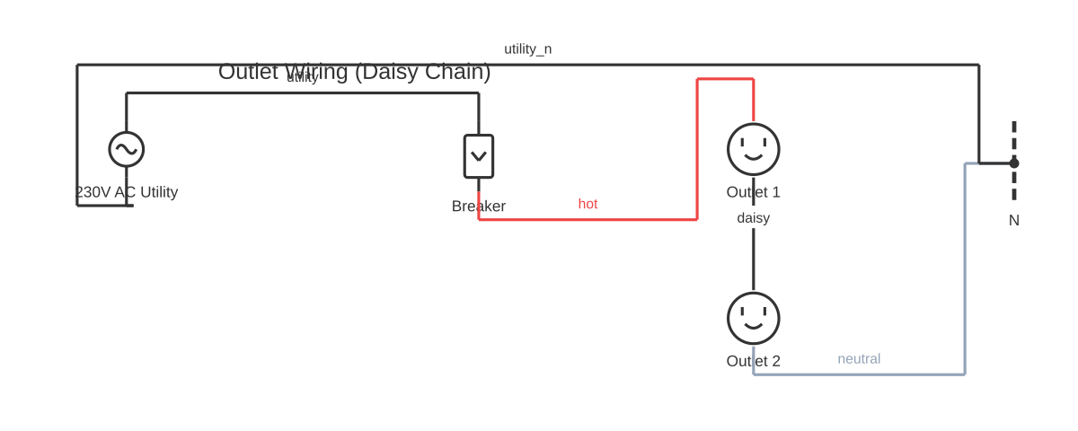
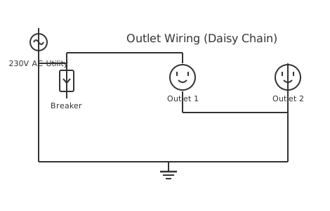
- Identify wiring configuration: end-of-run or loop (daisy-chain) End-of-run wiring: one cable enters the outlet box. The black wire connects to the hot terminal, the white to neutral, and the bare or green ground wire to the ground terminal. Loop (daisy-chain) wiring: two cables enter the box — the incoming supply cable and the outgoing cable continuing to the next outlet. On a standard receptacle, both hot wires join at the hot terminal (or use the screw terminal plus a pigtail), both neutrals at the neutral terminal, and both grounds at the ground terminal via a pigtail to a single terminal.
- For a GFCI receptacle, identify LINE and LOAD connections The LINE terminals are marked on the GFCI body and connect to the incoming supply wires. The LOAD terminals, if used, connect to the outgoing cable that feeds downstream receptacles requiring protection. If only this one receptacle needs GFCI protection (no downstream outlets on the LOAD terminals), connect only to the LINE terminals and leave the LOAD terminals with their protective tape in place.
- Connect conductors to terminals Strip conductors to the length indicated on the receptacle body gauge (typically 18 mm for screw terminals). For screw terminals, form a clockwise loop in the stripped conductor with needle-nose pliers so that tightening the screw draws the conductor under the screw head rather than pushing it out. Tighten screw terminals firmly — a poorly tightened terminal connection is the leading cause of receptacle overheating and fire. Connect ground first, then neutral, then hot.
- Fold wiring into the box and mount the receptacle Fold wires in an accordion pattern into the box — do not force wires into a compressed bundle, as this can crack insulation. Mount the receptacle in the box with the ground pin facing downward (North American convention) unless the box is oriented horizontally. Install the cover plate. Restore power and test the outlet with a socket tester: it should indicate correct wiring with no reversed polarity, no open ground, and no open neutral.
- Test GFCI operation with the TEST and RESET buttons For GFCI receptacles: press the TEST button — the RESET button should pop out and the outlet should lose power (verify with a socket tester or lamp in the outlet). Press RESET — the outlet should restore power. This confirms the GFCI mechanism is functioning. Test upstream GFCI protection for all downstream outlets connected to the LOAD terminals using the same procedure.
Specifications
| Standard North American residential receptacle ratings | 15 A, 120 V (NEMA 5-15R) or 20 A, 120 V (NEMA 5-20R) |
|---|---|
| UK standard socket outlet rating | 13 A, 230 V (BS 1363 with integral fuse in plug) |
| GFCI trip sensitivity | 4–6 mA residual current (North American standard per UL 943); 30 mA for RCD additional protection per IEC 60364 / BS 7671 |
| GFCI trip time at rated trip current | Less than 25 milliseconds (UL 943 Class A) |
| Wire gauge for 15 A circuit (NEC) | 14 AWG copper minimum |
| Wire gauge for 20 A circuit (NEC) | 12 AWG copper minimum |
| Applicable installation standards | NEC/NFPA 70 (USA), BS 7671 (UK), AS/NZS 3000 (Australia/NZ), IEC 60364 (international) |
Safety warnings
- Always verify the circuit is de-energised with a non-contact voltage tester and a multimeter before touching any conductors in an outlet box. Turning off the switch does not make the outlet safe if a switch-controlled outlet has more than one cable — the other cable may still be live.
- All receptacle wiring work must comply with the applicable electrical installation standard for your jurisdiction (NEC/NFPA 70, USA; BS 7671, UK; AS/NZS 3000, Australia and New Zealand; IEC 60364, international). In most jurisdictions, circuit extensions and new outlet installations require an electrical permit and inspection.
- Never connect aluminium wiring to receptacles designed for copper conductors only. Aluminium expands and contracts differently than copper — a direct termination at a copper-rated terminal creates a high-resistance joint that overheats under load. Aluminium wiring requires CO/ALR-rated devices and special connection procedures.
- Ground-fault circuit interrupter (GFCI) protection is required by code in wet locations — kitchens, bathrooms, garages, outdoors, crawl spaces, unfinished basements, and other areas specified in NEC 210.8 or equivalent provisions in your local standard. Omitting GFCI protection in required locations is a code violation and a serious shock hazard.
- Outlet boxes must not be overfilled with conductors. Each conductor, device, cable clamp, and fitting counts toward the box fill calculation per NEC 314.16 or equivalent. An overfilled box prevents the receptacle from seating correctly, damages conductor insulation, and is a fire hazard.
Tools needed
- Non-contact voltage tester (for initial circuit dead verification)
- Digital multimeter rated CAT II or CAT III (for thorough voltage and continuity testing)
- Flathead and Philips screwdrivers (receptacle and cover plate mounting)
- Needle-nose pliers (forming conductor loops for screw terminals)
- Wire stripper (for stripping conductors to correct length)
- Socket / outlet tester (plug-in type that indicates wiring correctness, reversed polarity, open ground)
- Voltage tester (non-contact type for initial live/dead check)
Common mistakes
- Reversed polarity — connecting the hot (black) conductor to the silver (neutral) terminal: this energises the wider neutral slot of the outlet, making the external shell of lamp bases live. It does not immediately trip the breaker and may go undetected without an outlet tester. Always connect black to brass and white to silver.
- Not pigtailing in loop (daisy-chain) wiring: connecting two conductors under one screw terminal is generally not permitted for the screw terminals on most receptacles (one conductor per screw is the standard). The correct method is to join both hot wires with a wire nut and a short pigtail, with the pigtail connecting to the receptacle's single screw terminal.
- Leaving the LOAD terminals unprotected on a GFCI where only LINE connection is intended: if the LOAD terminal wires are inadvertently left exposed without tape and contact something conductive in the box, it creates an unprotected parallel circuit path. Always tape over unused LOAD terminals.
- Using push-in backstab terminals on a high-current circuit: backstab terminals oxidise and loosen over time, particularly on 20 A circuits and with solid conductors that vibrate slightly due to wall movement. Overheated backstab connections are a common cause of outlet and wall fire incidents. Use screw terminals.
- Installing a 15 A receptacle on a 20 A circuit where code requires a 20 A outlet: NEC 210.21(B)(1) permits a single 15 A receptacle on a 20 A circuit under certain conditions, but where multiple receptacles are on a 20 A circuit serving kitchen countertops or similar locations, 20 A (T-slot, NEMA 5-20R) receptacles are required. Verify local code requirements.
Troubleshooting
- Outlet has no power; circuit breaker is on
- Cause: A tripped GFCI upstream in the circuit, a loose connection at this outlet or an upstream outlet in the daisy-chain, or an open neutral Fix: Press the RESET button on any GFCI outlet on the same circuit — even in another room. Check for any GFCI outlet or breaker that has tripped. If no GFCI is tripped, turn off the breaker, remove the outlet, and inspect the wire connections for loose terminals or broken conductors. An open neutral causes some outlets to be unpowered while a multimeter reads voltage across the slot — this indicates the neutral return path is open.
- Outlet tester shows reversed polarity
- Cause: The black (hot) conductor is connected to the neutral (silver) terminal and the white (neutral) conductor is on the hot (brass) terminal, or the black and white conductors in the cable have been transposed at a junction elsewhere in the circuit Fix: Turn off the circuit breaker and verify dead. Remove the outlet and swap the black and white conductors to their correct terminals (black to brass, white to silver). If the polarity indicator still shows reversed after correction at this outlet, the wiring upstream in the circuit has a transposition — trace back to the distribution panel or the nearest junction box.
- GFCI outlet will not reset — TEST button pops immediately
- Cause: A ground fault is present on the GFCI's own load circuit (either at a downstream outlet or within a connected appliance), or the GFCI unit has failed Fix: Unplug all devices from this outlet and any downstream outlets on the LOAD circuit. Attempt to reset — if the GFCI holds, reconnect devices one at a time to identify the faulty appliance. If the GFCI still will not reset with all devices unplugged, the fault is in the fixed wiring or the GFCI unit itself is faulty and requires replacement.
Frequently asked questions
How do I identify the hot, neutral, and ground terminals on a North American receptacle?
On a North American duplex receptacle: the brass-coloured screw terminal connects to the hot (black) conductor — it is on the side of the receptacle with the narrow slot. The silver-coloured screw terminal connects to the neutral (white) conductor — it is on the side with the wider slot. The green-coloured screw terminal (or green hex nut) connects to the ground (bare copper or green) conductor.
What is the difference between GFCI LINE and LOAD terminals?
The LINE terminals on a GFCI receptacle connect to the supply wiring from the distribution panel. These must always be connected for the GFCI to function. The LOAD terminals, if used, extend GFCI protection to any additional receptacles wired downstream (daisy-chained after the GFCI in the same circuit). Downstream receptacles connected to the LOAD terminals do not themselves need to be GFCI devices — they receive protection from the upstream GFCI.
What happens if I wire a receptacle with reversed polarity (hot to neutral terminal)?
Reversed polarity means the neutral slot of the outlet is live and the hot slot is at neutral potential. Many appliances will still appear to function normally — but the outer shell of lamp holders and some appliance chassis will be energised when the appliance switch is open. This presents a shock hazard during routine lamp changing and maintenance. Polarised appliance plugs are designed to prevent reversed polarity at the appliance's internal switch — this safety feature is defeated by a reversed-polarity outlet.
Why is a GFCI outlet required in kitchens and bathrooms?
Water significantly reduces skin resistance, which substantially increases the current that flows through a person contacting a live conductor. A standard overcurrent breaker (15 A or 20 A) will not trip fast enough to prevent a fatal shock from a current as low as 10–50 mA through the body. A GFCI detects imbalance currents as low as 4–6 mA and trips within 25 ms — fast enough to prevent fibrillation in most cases. NEC and most IEC-based codes mandate GFCI protection in wet areas for this reason.
Can I use the side-stab (push-in) terminals on a receptacle instead of the screw terminals?
Side-stab or push-in backstab terminals on receptacles are convenient but are a well-known source of high-resistance connections that loosen over time, especially with stranded conductors. Most professional electricians and electrical codes recommend using the screw terminals for a more reliable mechanical and electrical connection. If push-in terminals are used, they must be used only with solid copper conductor of the appropriate gauge — they are not suitable for aluminium wiring.
How do you wire a receptacle outlet correctly?
Connect the black (hot) wire to the brass-coloured screw on the side with the narrow slot, the white (neutral) wire to the silver-coloured screw on the side with the wider slot, and the bare or green ground wire to the green screw. Tighten terminals to the torque value stamped on the device (typically 12–14 in-lb for screw terminals). If back-wiring (push-in terminals) is used, only the holes rated for the conductor gauge should be used; screw terminals are generally the more reliable connection method for long-term use.
Related diagrams
- 0 10v led dimming wiring diagram
- 1 4 stereo jack wiring diagram
- 1 gang 1 way switch wiring diagram
- 1 gang 2 way switch wiring diagram
- 1 ohm sub wiring diagram
- 1 ohm wiring diagram