Understanding Relay Symbols in Electrical Schematics
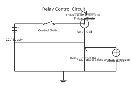
This is a free printable relay schematic diagram: download the diagram as SVG or open it and print to paper or PDF.
A relay schematic diagram uses standardized symbols to show relay coils and contacts separate from each other for clarity in complex circuits.
Diagram checks and scope
- Components
- 7
- Wired connections
- 9
- Automated check
- Automated pin, route, source, and topology checks passed; this is not a safety certification.
Relay schematic diagrams employ a convention where the relay coil is shown separately from its contacts, even though they are physically part of the same device. This separation allows clear representation of control circuits at one location and power circuits at another. The coil is shown as a rectangle with text designation like K1, K2 for identification. All contacts associated with that coil are shown elsewhere in the diagram with the same reference designation. Normally open (NO) contacts are shown as two vertical lines with a gap, indicating no current path when inactive. Normally closed (NC) contacts show a diagonal line closing the gap, indicating current flows when inactive. Changeover contacts show a vertical line connecting to two different positions, allowing selection between two circuits. Multiple contacts from a single relay are identified with numbers: K1-1 for first contact, K1-2 for second contact. Contact numbering follows the sequence: pin 1 is the contact arm, pins 2 and 4 are NO connections, pin 3 is NC connection. Understanding this notation enables accurate wiring from schematic diagrams. Color-coded conductors in the actual circuit correspond to line numbers in the schematic. Testing circuit operation requires understanding which schematic paths correspond to physical wiring runs.
How to wire relay schematic diagram
- Locate the relay coil on the schematic diagram and note its reference designation (K1, K2, etc.)
- Find all contacts associated with that relay using the same reference designation throughout the diagram
- Trace control circuit paths that energize the coil through switches and permissive contacts
- Trace power circuit paths controlled by the relay contacts to determine load operation
- Verify that contact configuration (NO or NC) matches the desired control logic
Frequently asked questions
Why are relay coils shown separate from contacts?
Separation clarifies control circuits from power circuits and shows all contacts operating from one coil.
What do the numbers mean on relay contact symbols?
Numbers indicate contact position, typically 1=common, 2=NO connection, 3=NC connection, 4=NO connection.
How do I identify which contacts belong to which coil?
Contact symbols near schematic locations are labeled with the same reference as the coil: K1, K2, etc.
What is the difference between a relay and a contactor?
Relays handle small currents in control circuits, contactors handle high power currents in motor circuits.
How do I trace a relay control function through a schematic?
Follow the same reference designation from coil to all associated contacts, noting which are engaged when coil is energized.
Sources and verification
Review status: Not independently reviewed. Automated topology checks confirm stored terminals and routes, not the correctness of manufacturer pin assignments, ratings, regional codes, or installation decisions. Verify those claims against the current primary documentation before use.
- IEC 61082-1:2014 — Rules for electrotechnical documents — International Electrotechnical Commission. Supports: General diagram, drawing, table, and reference-designation presentation conventions. Checked 2026-07-15.
Related diagrams
- 12v 5 pin relay wiring diagram
- 12v relay pinout
- 4 pin relay wiring
- 4 pin relay wiring diagram for lights
- 4 pin relay wiring diagram with switch
- 5 pin relay pinout