single phase motor diagram
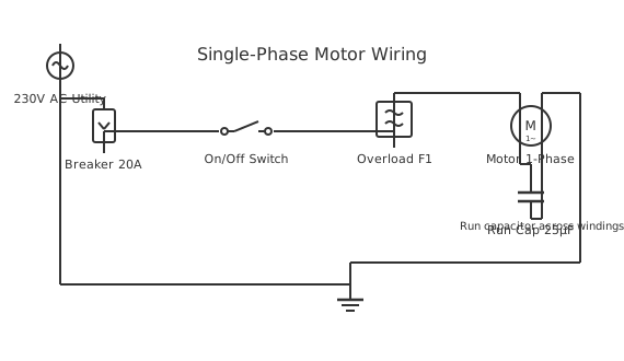
This is a free printable single phase motor diagram: download the diagram as SVG or open it and print to paper or PDF.
Diagram checks and scope
- Components
- 7
- Wired connections
- 8
- Automated check
- Automated pin, route, source, and topology checks passed; this is not a safety certification.
A single-phase motor diagram depicts the wiring configuration for AC motors operating on standard residential 120-volt or 240-volt single-phase power, showing the main winding, auxiliary starting winding, and centrifugal switch that disconnects starting components after motor acceleration. The diagram illustrates how phase-split capacitor motors generate rotating magnetic fields without requiring three-phase power, making them ideal for household and small commercial applications. Single-phase motors are more complex than DC motors but simpler than three-phase industrial motors, representing the most common motor type found in residential HVAC systems, refrigeration, and small machinery. The diagram shows the capacitor's critical role in shifting current between main and start windings to create rotation, with typical capacitor sizes ranging from 5 to 50 microfarads. Starting capacitors handle high voltages only briefly during startup, while running capacitors operate continuously and require different designs. Understanding single-phase motor circuits enables diagnosis of common failure modes including capacitor degradation, winding insulation breakdown, and bearing wear.
How to wire single phase motor diagram
- Read the motor nameplate Record voltage, current (FLC), frequency, speed (RPM), power output (kW), insulation class, and IP rating. The nameplate determines every wiring and protection decision. A missing or illegible nameplate requires meggering and testing before use.
- Identify terminal designations Open the terminal box. Single-phase motors typically have terminals: L1, L2 (or N) for main supply, plus terminals for the start/run capacitor. Some have separate main and auxiliary winding terminals U1, U2, Z1, Z2.
- Connect supply conductors Connect phase (brown/live) to L1 and neutral (blue) to L2 or N. Connect earth (green/yellow) to the motor frame earth terminal. Do not skip the earth — a single-phase motor fault without earth protection gives a full 230V shock.
- Connect the capacitor Connect the run capacitor across the designated capacitor terminals as shown on the motor's wiring diagram label (usually inside the terminal box cover). Incorrect capacitor connection causes low starting torque and motor overheating.
- Fit overload protection Install a thermal overload relay or motor-rated MCB in the supply circuit, set to the motor's FLC. For pumps and compressors running unattended, use a manual-reset overload — automatic reset can restart a motor into a fault condition.
- Test run and check current Apply supply and check that the motor starts cleanly without hesitation. Using a clamp meter, measure running current — it should be at or below FLC. Higher-than-rated current indicates overloading, incorrect capacitor, or winding fault.
Frequently asked questions
Why does a single-phase motor need a start capacitor?
A single-phase AC supply produces a pulsating magnetic field, not a rotating one. The start capacitor shifts the phase of current in the auxiliary winding by about 90 degrees, creating a two-phase effect that produces starting torque and gets the rotor spinning.
What is the difference between a start capacitor and a run capacitor?
A start capacitor is rated for intermittent duty only — it disconnects via a centrifugal switch once the motor reaches speed. A run capacitor stays in circuit permanently, improving power factor and efficiency. They have different voltage and capacitance ratings and are not interchangeable.
How do I reverse a single-phase motor?
Swap the connections of either the main winding or the auxiliary winding — not both. Most motor terminal boxes have labels (M1, M2 for main; A1, A2 for aux) to guide this. Swapping both windings does nothing — the rotation stays the same.
Why does a single-phase motor hum but not start?
The start capacitor has failed, the centrifugal switch is stuck open, or the auxiliary winding is open circuit. Confirm by trying to hand-start the motor — give the shaft a spin in the correct direction with the power on. If it runs, the start circuit is the problem.
What overload protection does a single-phase motor need?
A single-phase motor needs an overload relay or thermal cutout sized to the motor's FLC. Many small single-phase motors have a built-in thermal protector that resets automatically — but automatic reset on an unattended pump or compressor is a fire risk.
Sources and verification
Review status: Not independently reviewed. Automated topology checks confirm stored terminals and routes, not the correctness of manufacturer pin assignments, ratings, regional codes, or installation decisions. Verify those claims against the current primary documentation before use.
- IEC 61082-1:2014 — Rules for electrotechnical documents — International Electrotechnical Commission. Supports: General diagram, drawing, table, and reference-designation presentation conventions. Checked 2026-07-15.
Related diagrams
- 220v single phase motor wiring diagram
- 3 phase motor to single phase wiring diagram
- 3 wire single phase motor connection
- 4 lead single phase motor wiring diagram
- 6 lead single phase motor wiring diagram with capacitor
- 6 wire single phase motor wiring diagram