Three Way Switch Connection
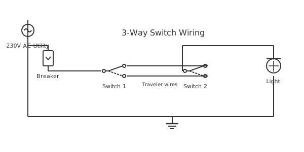
This is a free printable three way switch connection: download the diagram as SVG or open it and print to paper or PDF.
This complete guide to the three way switch connection explains circuit operation, component selection, safety requirements, and step-by-step installation procedures for professional and advanced DIY use.
Diagram checks and scope
- Components
- 6
- Wired connections
- 7
- Automated check
- Automated pin, route, source, and topology checks passed; this is not a safety certification.
Understanding the three way switch connection circuit requires recognising how each subsystem contributes to overall system reliability and safety. Power conditioning elements at the source remove voltage spikes, harmonic distortion, and transients that would otherwise stress insulation and degrade electronic component life. Surge protective devices (SPDs) clamp transient voltages caused by lightning, utility switching events, or inductive load switching. Line reactors reduce harmonic distortion from variable frequency drives, extending capacitor and transformer service life. The switching or control section manages power delivery to the load: electromechanical contactors handle high-current loads where reliability and visual inspection of contact condition are priorities, while solid-state relays (SSRs) switch rapidly without contact wear for high-cycle applications. The load section must include thermal protection -- overload relays or thermistors embedded in motor windings -- to detect abnormal heating before damage occurs. Monitoring elements such as current transformers, power quality analysers, and PLCs with analog input modules provide real-time visibility into circuit operating conditions, enabling trend analysis and predictive maintenance. Grounding architecture ensures a single low-impedance reference point for all equipment: separate equipment ground conductors run back to the panel, never sharing neutral conductors, to avoid neutral-current-induced voltage on exposed metal. Emergency stop circuits use normally closed contacts in series so any wiring break or switch failure results in a safe stop state.
How to wire three way switch connection
- Review the circuit diagram Study the complete three way switch connection diagram, identifying power source, protection, loads, and ground path before purchasing any materials.
- Calculate and select components Size the breaker, wire gauge, and load devices according to calculated demand plus 25% safety margin for continuous loads.
- Install conduit or cable route Run EMT conduit or NM cable along the planned route, securing every 4.5 ft per NEC 334.30. Protect cable from physical damage with conduit where exposed.
- Make all connections Connect conductors to terminals in sequence: ground first, then neutral, then hot. Torque all terminals to specification on the device label.
- Install overcurrent protection Install the correctly rated breaker in the panel. Verify the breaker matches the wire gauge and load requirements.
- Test before energising Test continuity of all conductors. Verify insulation resistance. Confirm ground continuity from load enclosure to panel.
- Energise and verify Turn on the breaker. Measure voltage at the load terminals. Verify load operates correctly. Check for unusual heat at any connections after 15 minutes.
Specifications
| Nominal voltage | 120 V or 240 V AC (single phase) |
|---|---|
| Typical circuit rating | 15-30 A |
| Conductor material | Copper (THHN or NM-B) |
| Ground conductor | Same gauge as circuit conductors |
| Maximum voltage drop | 3% branch circuit (NEC recommendation) |
Safety warnings
- Always de-energise the circuit at the breaker and verify zero volts with a calibrated meter before touching any wiring in a three way switch connection circuit.
- Do not exceed the rated current of conductors or protective devices -- overcurrent causes insulation failure and fire in three way switch connection installations.
- Maintain proper grounding on all metal enclosures and equipment frames to prevent shock hazard if insulation fails.
Tools needed
- Digital multimeter (voltage, current, continuity, and resistance)
- Wire stripper, crimper, and torque screwdriver
- Non-contact voltage tester for live-circuit verification
- Electrical code reference (NEC or applicable local standard)
Common mistakes
- Connecting the neutral and ground conductors together at a point other than the main service panel -- downstream neutral-ground bonds create dangerous ground-loop currents.
- Using incorrect wire gauge for the circuit amperage -- always consult NEC Table 310.15 and apply a 125% margin for continuous loads.
- Forgetting to torque terminal screws to specification -- loose connections create resistance, heat, arcing, and eventual fire.
Troubleshooting
- Circuit breaker trips immediately
- Cause: Short circuit (hot touching neutral or ground) in wiring or load Fix: Disconnect load. Re-energise breaker. If it holds, fault is in the load device. If it still trips, short is in the fixed wiring -- inspect connections.
- Load operates but voltage is low
- Cause: High resistance connection or undersized wire causing excessive voltage drop Fix: Measure voltage at panel and at load. Calculate drop. Inspect connections for corrosion or loose terminals. Upsize wire if drop exceeds 3%.
- Breaker trips under load but not immediately
- Cause: Overloaded circuit (current exceeds breaker rating for sustained period) Fix: Calculate total circuit load. Distribute loads to additional circuits. Do not replace breaker with larger rating without upsizing wire.
Frequently asked questions
What is the correct wire size for a three way switch connection circuit?
Wire size depends on circuit amperage and run length. For 15 A circuits use 14 AWG; for 20 A use 12 AWG; for 30 A use 10 AWG. Always check NEC Table 310.15(B)(16) for the exact ampacity based on conductor type and installation method. For runs over 100 feet apply a voltage-drop calculation to ensure terminal voltage stays within 3% of nominal.
How do I test a three way switch connection circuit for faults?
De-energise the circuit at the breaker. Use a multimeter in resistance mode to check continuity through each conductor. Use an insulation resistance tester (megohmmeter) at 500 V to verify insulation resistance exceeds 1 megohm. Re-energise and measure voltage at the load terminals. Compare measured voltage to nominal; more than a 3% drop indicates undersized wire or a poor connection.
Is a ground fault circuit interrupter (GFCI) required on this circuit?
NEC 210.8 requires GFCI protection in bathrooms, kitchens, garages, outdoors, crawl spaces, unfinished basements, near swimming pools, and other damp locations. If your installation is in any of these areas, GFCI protection is mandatory. GFCI devices trip at 5 mA of ground-fault current, providing personal shock protection far below the overcurrent device trip level.
What causes voltage drop in this installation?
Voltage drop is caused by conductor resistance combined with load current: V_drop = I times R. Long cable runs, undersized conductors, loose terminal connections, and high contact resistance all contribute. The NEC recommends keeping voltage drop below 3% for branch circuits and 5% total for branch plus feeder. Increase conductor size or reduce run length to correct excessive voltage drop.
How often should this installation be inspected?
Residential circuits should be visually inspected annually and tested every 5-10 years by a licensed electrician. Commercial and industrial installations follow NFPA 70B maintenance schedules: visual inspection every 12 months, thermographic scan every 36 months, insulation resistance test every 5 years. Any circuit that has been wet, overloaded, or subjected to physical damage requires immediate inspection before re-energising.
Sources and verification
Review status: Not independently reviewed. Automated topology checks confirm stored terminals and routes, not the correctness of manufacturer pin assignments, ratings, regional codes, or installation decisions. Verify those claims against the current primary documentation before use.
- IEC 61082-1:2014 — Rules for electrotechnical documents — International Electrotechnical Commission. Supports: General diagram, drawing, table, and reference-designation presentation conventions. Checked 2026-07-15.
Related diagrams
- three way light switch diagram
- wiring a three way switch
- eaton 3 way switch diagram
- legrand 3 way switch
- 1 gang 1 way switch wiring diagram
- 1 gang 2 way switch wiring diagram