timer relay wiring diagram
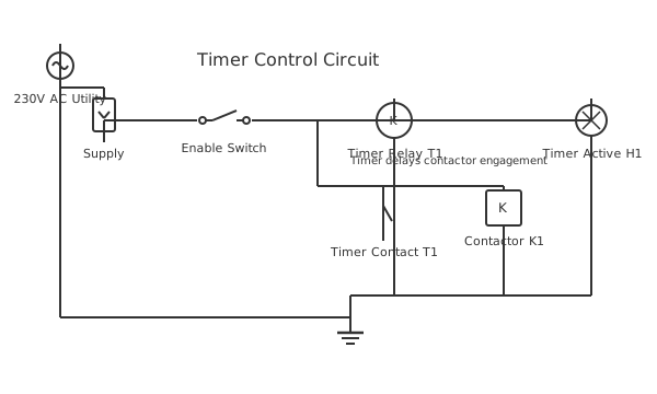
This is a free printable timer relay wiring diagram: download the diagram as SVG or open it and print to paper or PDF.
Diagram checks and scope
- Components
- 8
- Wired connections
- 10
- Automated check
- Automated pin, route, source, and topology checks passed; this is not a safety certification.
A timer relay wiring diagram demonstrates how an electromechanical or electronic relay with built-in time-delay functionality controls circuits that require delayed activation or deactivation. The diagram shows: control input signal (12V or 24V) energizing the timer relay coil, internal timing circuit (mechanical cam or electronic circuit) delaying contact closure by a preset interval, and the delayed contact output switching the load circuit. Timer relays are essential for: HVAC systems delaying fan startup until furnace heat exchanger reaches operating temperature (preventing cold air circulation), motor soft-starts limiting inrush current when the motor initially energizes, and sequential control circuits activating multiple loads in predetermined sequence. The diagram identifies: control input connector, time delay potentiometer or selector switch (adjustable from milliseconds to minutes), normally-open contact output for load switching, and coil power supply. Electronic timer relays offer more precise timing (±1%) and multiple timing functions: ON-delay (contact closes after timer expires), OFF-delay (contact opens after timer expires), and repeat-cycle timers for periodic operation. Understanding timer relay operation enables proper installation in HVAC systems, soft-start applications, and industrial automation sequences.
How to wire timer relay wiring diagram
- Select the correct timer relay mode Before wiring, set the mode selector on the timer relay face to on-delay, off-delay, or cyclic as required by your application. Wrong mode means the output behaves backwards.
- Connect control supply to A1 and A2 Wire your 220V AC (or 24V DC) control supply to terminals A1 and A2 on the timer relay. Include a 6A fuse on the supply line before the relay.
- Wire the trigger input if required For externally-triggered timers, connect your trigger switch or sensor signal to the designated trigger terminals. Maintained-contact triggers suit on-delay; momentary triggers suit pulse modes.
- Connect the output contact to the load or contactor coil Wire terminal 1 (common), 3 (NO), or 4 (NC) to your load circuit. For heavy loads, wire the NO contact in series with a contactor coil rated for the actual load.
- Set the time delay Adjust the timing dial or DIP switches to the required delay. Most relays have a multiplier switch (x1, x10, x100) — confirm the multiplier position matches your intended time range.
- Wire the indicator lamp Connect an LED pilot lamp across the output contact load terminals so you can see when the timer output is active. This makes fault-finding significantly faster on site.
- Test timing accuracy with a stopwatch Apply trigger signal and time the output with a stopwatch. Adjust the dial if actual delay differs from set value. Some relays drift 10–15% at the extremes of their range.
Frequently asked questions
What is the difference between on-delay and off-delay timer wiring?
On-delay: output energises after the set time once trigger is applied. Off-delay: output de-energises after the set time once trigger is removed. Most timer relays switch between modes via a front panel selector — the wiring is identical, only the mode changes.
Can I use a timer relay to control a 380V three-phase load directly?
No. Timer relay output contacts are typically rated 8–16A at 250V AC. Wire the timer relay output contact to a suitably rated 3-phase contactor coil instead. The contactor then switches the heavy three-phase load.
My timer keeps resetting before the cycle completes. What is wrong?
The trigger input is likely losing power intermittently. Check whether your trigger switch is a maintained contact or a momentary contact and match that to the timer relay's trigger type setting. Voltage dips during load switching can also cause false resets.
How do I wire a repeat cycle (interval) timer?
Select cyclic mode on the timer relay. Connect supply to A1/A2 coil terminals. Wire the output contact NO in series with your load or contactor coil. The timer will self-oscillate between its on-time and off-time settings without needing an external trigger.
What supply voltage do timer relays typically accept?
Most industrial timer relays accept a wide input range — 24V DC, 110V AC, or 220V AC selectable via internal links or separate model variants. Always verify the timer relay supply voltage matches your control circuit before wiring.
Sources and verification
Review status: Not independently reviewed. Automated topology checks confirm stored terminals and routes, not the correctness of manufacturer pin assignments, ratings, regional codes, or installation decisions. Verify those claims against the current primary documentation before use.
- IEC 61082-1:2014 — Rules for electrotechnical documents — International Electrotechnical Commission. Supports: General diagram, drawing, table, and reference-designation presentation conventions. Checked 2026-07-15.
Related diagrams
- 12v timer relay wiring diagram
- 8 pin timer relay wiring diagram
- 12v 5 pin relay wiring diagram
- 12v relay pinout
- 4 pin relay wiring
- 4 pin relay wiring diagram for lights