Two Way Light Switch Wiring Diagram — Visual Installation Guide
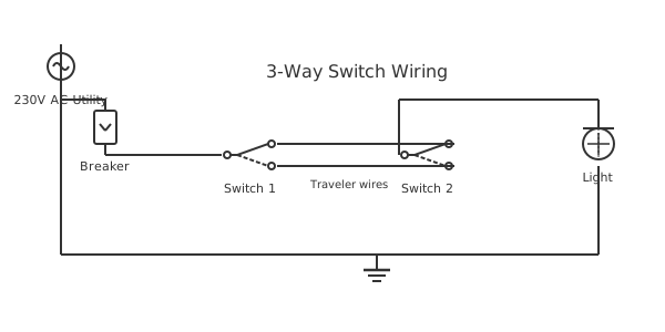
This is a free printable two way light switch wiring diagram: download the diagram as SVG or open it and print to paper or PDF.
A two-way light switch wiring diagram enables a single light fitting to be controlled from two separate locations — essential for staircases, hallways, and dual-entry rooms. This visual guide explains every cable, every terminal, and every connection needed for a professional two-way light switch installation that works reliably and meets electrical safety standards.
Diagram checks and scope
- Components
- 6
- Wired connections
- 7
- Automated check
- Automated pin, route, source, and topology checks passed; this is not a safety certification.
Two-way light switch wiring is one of the most frequently installed circuits in domestic electrical work and one of the most frequently wired incorrectly. The fundamental principle is that two single-pole double-throw (SPDT) switches share two common conductor paths — the strap or traveler wires — and together control whether the lamp circuit is complete or open. At any given time, the two switches either route through the same traveler (circuit complete, lamp ON) or through different travelers (circuit open, lamp OFF). Flipping either switch toggles the state. The visual diagram typically shows three cable sections: the supply cable from the consumer unit or distribution board into the first switch position, a three-conductor cable between the two switch positions, and a cable from the second switch to the light fitting. Understanding how the neutral flows separately from the live is critical: the neutral wire runs from the consumer unit through to the light fitting without connecting to any switch terminal. The live wire enters Switch 1 at the common terminal. Two strap wires (the three-conductor cable minus one, used as neutral in some configurations or unused) bridge between the two switches. The switched live exits Switch 2 at the common terminal and feeds the lamp. Modern smart switching systems — including Lutron Caseta, Philips Hue, and Legrand Adorne — replace this physical traveler wire system with wireless communication between smart switches, requiring only the live, neutral, and earth at each switch position, simplifying installation in existing buildings where running new three-conductor cables between boxes would be impractical. For retrofit installations in buildings with junction box wiring (older UK installations), the diagram must also account for the junction box connections that distribute the live, neutral, and switched live between the ceiling rose and the switch positions.
How to wire two way light switch wiring diagram
- Confirm cable routes and box positions Mark both switch positions on the wall. Use a cable detector to verify no existing cables are in the planned chasing route. Confirm box depths — standard 35mm depth for twin-and-earth installations.
- Install back boxes and route cables Fit back boxes at both switch positions. Run twin-and-earth from consumer unit to Switch 1 box. Run three-core-and-earth between Switch 1 and Switch 2 boxes. Run twin-and-earth from Switch 2 box to ceiling rose or fitting.
- Prepare all conductors Strip 75mm of outer sheath from each cable inside each box. Strip 10mm of insulation from each conductor. Fit green/yellow sleeving on bare earth conductors. Mark any conductors used as switched live with brown sleeving.
- Connect Switch 1 and Switch 2 SW1: live to L1, first strap to L2, second strap to L3, earth to earth terminal. SW2: first strap to L2, second strap to L3, switched live to L1, earth to earth terminal. Fold conductors into boxes and secure switches.
- Connect fitting and commission At ceiling rose: switched live to live terminal, neutral to neutral, earth to earth. Restore MCB. Test lamp from both switch positions. Confirm ON/OFF toggles with each switch independently.
Specifications
| Circuit standard | BS 7671 (UK) / NEC (US) |
|---|---|
| Strap cable type | 3-core + earth between switches |
| UK switch rating | 6A 250V, BS EN 60669 |
| Typical lamp load | LED 5-15W, max 1380W at 6A/230V |
Safety warnings
- In staircase installations, ensure lighting operates before the stairs are used — do not leave staircases without functional lighting at any point during installation.
- Test the RCD (residual current device) protecting the lighting circuit before and after work — two-way switch wiring involves opening and reconnecting circuit conductors that must be protected.
- If rewiring or extending into an older installation, check for asbestos in ceiling rose pattresses and switch back boxes before disturbing them — particularly in pre-1980 buildings.
Tools needed
- Approved voltage indicator and multimeter
- Wire stripper for 1.0-1.5mm² cable
- Cable detector (before drilling or chasing)
- Pozidriv and flathead screwdrivers
Common mistakes
- Connecting the neutral to the switch common (L1) — the neutral must bypass the switches entirely and run directly to the lamp; connecting it to a switch interrupts the neutral and can cause the lamp to glow dimly at all times due to capacitive coupling.
- Installing the three-core cable backwards so the wrong switch becomes the supply-side switch — functionally identical but reverses the installation logic and confuses future work.
- Not providing a sufficient service loop inside each switch box — wires that are cut too short cannot be remade if terminals are damaged, requiring cable replacement.
Troubleshooting
- Lamp glows dimly when switched off
- Cause: Neutral connected to switch common instead of running directly to fitting — capacitive coupling through the switch creates a small leakage current Fix: Trace the neutral at both switch boxes. The neutral must not connect to any switch terminal. Re-route neutral directly from supply to fitting without interruption at either switch.
- Switch 1 has no effect but Switch 2 toggles correctly
- Cause: Both strap wires connected to the same terminal (L2 or L3) at Switch 1 — the switch has no second path to route through Fix: Verify Switch 1 has one strap wire on L2 and one on L3. If both are on the same terminal, move one to the other terminal.
- Lamp buzzes when on
- Cause: Dimmer switch installed in a two-way circuit with an incompatible LED lamp, or a loose terminal causing arcing Fix: If a dimmer is used, confirm it is rated for LED loads and the lamp is dimmable-LED rated. If not a dimmer circuit, inspect all terminals for loose connections that might arc.
Frequently asked questions
How does a two-way light switch actually control the light?
Each switch connects its common terminal to one of two strap wires. The circuit is complete when both switch commons are on the same strap wire — current flows: supply live → Switch 1 common → strap wire → Switch 2 common → switched live → lamp → neutral → supply. Flipping either switch moves its common to the other strap wire, breaking the path. The magic is that either switch can create or break the path.
Can I use smart switches for two-way control without running new cables?
Yes — wireless smart switches communicate by radio instead of traveler wires. One switch is the primary (requires live and neutral) and the other is a remote (battery powered or using existing cable for power only). Install the primary at the supply-side location and the remote at the other. No three-conductor cable between switches is required, making retrofit installations in existing buildings practical.
What is the current UK harmonised cable color code for two-way switch wiring?
Current harmonised colors (since 2004): Line/Live = brown, Neutral = blue, Earth = green/yellow. In three-core-and-earth between switches: brown, black, grey conductors (black and grey used as strap wires, not neutrals). Old colors (pre-2004): red=live, black=neutral, green/yellow=earth, and in three-core: red, yellow, blue with bare earth. Always identify old cable colors before assuming the color meaning.
How do I add a second light to an existing two-way switch circuit?
The easiest method: at the first fitting, connect the second fitting in parallel — run a cable from the first fitting live and neutral terminals to the second fitting's corresponding terminals. Both fittings will now be controlled together by the same two-way switch circuit. This works as long as the total current of both fittings does not exceed the circuit MCB rating. If separate control is needed, a new dedicated circuit is required.
My two-way switch worked and then stopped — what failed?
The most common sudden failures are: a blown lamp (check first), a tripped MCB or blown fuse, or a loose/broken wire at a switch terminal. Inspect both switch boxes for a wire that has pulled out of its terminal — vibration from slamming doors is a common cause in staircase circuits. A terminal that was never properly secured will eventually vibrate loose. Remake all connections with correctly stripped wire and verify tightness.
Sources and verification
Review status: Not independently reviewed. Automated topology checks confirm stored terminals and routes, not the correctness of manufacturer pin assignments, ratings, regional codes, or installation decisions. Verify those claims against the current primary documentation before use.
- IEC 61082-1:2014 — Rules for electrotechnical documents — International Electrotechnical Commission. Supports: General diagram, drawing, table, and reference-designation presentation conventions. Checked 2026-07-15.
Related diagrams
- 1 way light switch wiring diagram
- 2 way light switch wiring
- 3 way light switch wiring
- 4 way light switch diagram
- three way light switch diagram
- two way switch circuit