2 Way Light Switch Wiring Diagram — UK, AU & International Method
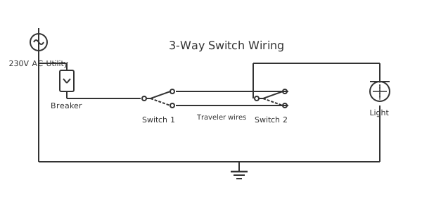
This is a free printable 2 way light switch wiring diagram: download the diagram as SVG or open it and print to paper or PDF.
A 2-way light switch wiring diagram shows how two switches connect to control a single light from two locations — the standard method for staircases, hallways, and large rooms in UK, Australian, and European electrical installations. The UK/AU "2-way" is equivalent to the US "3-way" circuit concept, using two single-pole double-throw (SPDT) switches linked by two strap wires. This guide explains UK-standard connections using the modern harmonised cable color code.
Diagram checks and scope
- Components
- 6
- Wired connections
- 7
- Automated check
- Automated pin, route, source, and topology checks passed; this is not a safety certification.
In UK, Australian, and many international electrical installations, controlling a light from two locations uses what is locally called a "2-way switching" arrangement — called "3-way" in US terminology. The terminology difference: in the UK, a switch's "way" refers to how many output positions it has, so a 2-way switch connects to one of two possible outputs. Two such switches wired together give two-location control. UK wiring conventions under the harmonised cable color code (since 2004) use brown for line (live), blue for neutral, and green/yellow for earth. The older harmonised colors (red=live, black=neutral) are still found in older buildings and must be identified carefully before work. A 2-way switch has three terminals: L1 (common, where live enters or the load exits), and two strapping terminals labeled L2 and L3 (or COM and two travelers in some labeling). Two strap wires — sometimes called strappers — connect L2 of Switch 1 to L2 of Switch 2, and L3 of Switch 1 to L3 of Switch 2. These four connections form the core of the 2-way circuit. The live (brown/red) from the consumer unit feeds the L1 of Switch 1. The switched live leaves Switch 2 from its L1 terminal and goes to the light fixture line terminal. The neutral (blue/black) runs directly from the consumer unit or light fitting terminal to the fixture neutral, not through either switch. The earth (green/yellow) connects to the earth terminal of each switch, the light fitting, and continues to the consumer unit earth bar. Modern rewirable installations should use the current harmonised color code. Always test with a voltage indicator before touching any wire — in 2-way circuits, the strap wires may be live depending on switch positions.
How to wire 2 way light switch wiring diagram
- Isolate and verify dead Switch off the circuit at the consumer unit. Test all cables in both switch boxes with an approved voltage indicator. Verify all conductors read zero before proceeding.
- Connect Switch 1 (supply side) Brown (live from consumer unit) → L1 terminal of Switch 1. Run the first strap wire (orange or brown) from L2 of Switch 1 to L2 of Switch 2. Run the second strap wire (yellow or grey) from L3 of Switch 1 to L3 of Switch 2. Earth → switch earth terminal.
- Connect Switch 2 (fixture side) L2 and L3 ← strap wires from Switch 1. Brown switched live (to fixture) → L1 of Switch 2. Earth → switch earth terminal.
- Wire the light fitting Switched live (brown, from Switch 2 L1) → light fitting live terminal. Neutral (blue, direct from consumer unit) → light fitting neutral terminal. Earth → light fitting earth.
- Test 2-way operation Restore supply. Verify the light operates correctly from both switch positions. Test all four switch position combinations — two should give ON and two should give OFF.
Specifications
| UK switch standard | BS EN 60669-1 |
|---|---|
| Live (line) color | Brown (harmonised) / Red (old) |
| Neutral color | Blue (harmonised) / Black (old) |
| Switch rating | 6A or 10A, 230V AC |
Safety warnings
- In the UK, only competent persons under Part P of the Building Regulations may carry out certain electrical work — check if notification or inspection is required for your specific work.
- Never work on live circuits — isolate at the consumer unit and use a voltage indicator (GS38 approved) to confirm all conductors in the switch box are dead before touching them.
- Identify old cable colors correctly before working on pre-2004 installations — old red may be marked with brown tape to indicate it has been re-identified as live in some installations.
Tools needed
- Approved voltage indicator (GS38 compliant, not just a neon screwdriver)
- Flathead and Pozidriv screwdrivers
- Wire stripper for 1.0 and 1.5mm² cable
- Multimeter for continuity testing
Common mistakes
- Connecting the strap wires to the L1 (common) terminal instead of L2 and L3 — this defeats the 2-way function and causes permanent energization or complete failure.
- Using only one strap wire between switches — a single-strap connection creates an intermediate switch but not true 2-way operation from both locations.
- Connecting neutral to the switch common instead of running it directly to the fixture — the neutral must not be interrupted by any switch.
Troubleshooting
- Light stays on permanently from one switch, other has no effect
- Cause: Strap wires connected to L1 of one switch instead of L2 and L3 — creating a permanent connection Fix: Isolate supply. Move the strap wires from L1 to the correct L2 and L3 terminals on that switch.
- No operation from either switch location
- Cause: Open circuit in the live feed, a strap wire not connected, or neutral not reaching the fixture Fix: Check live at Switch 1 L1 with supply on. Then check strap wire continuity with supply off. Verify neutral is connected at the fixture.
- Switches control the light but in reversed logic
- Cause: Strap wires L2 and L3 are crossed at one switch — functionally correct but reversed convention Fix: Swap the two strap wires at either switch. The circuit will function identically but with standard switch positions.
Frequently asked questions
What is the difference between a 1-way and 2-way light switch?
A 1-way (one-way) switch has two terminals — it simply opens or closes the circuit like an on/off switch. A 2-way switch has three terminals (L1 common, L2 and L3) — it connects L1 to either L2 or L3, allowing the switch to route current along two different paths. A single 2-way switch used alone functions as a 1-way switch (ignoring one of the L2/L3 terminals). Two 2-way switches linked by strap wires give two-location control.
What wire colors are used in UK 2-way switch wiring?
Current harmonised colors: Line/Live = brown, Neutral = blue, Earth = green/yellow. The strap wires between switches are typically orange and yellow in older 3-core and earth cable, or brown and grey in modern installations using twin-and-earth with additional core. The switched live running from Switch 2 L1 to the fixture should be identified as live — mark it with brown sleeving if it is any other color.
Can I use a 1-way switch in place of a 2-way switch?
Only if you are removing the two-location control entirely and want control from one location only. A 1-way switch cannot be used as part of a 2-way circuit because it lacks the third L1 terminal needed for the strap connection. If replacing a 2-way switch with a 1-way, cap the two strap wires and connect only the L1 (live in, switched live out) connections.
How do I test which terminal is L1 (common) on an unlabeled switch?
Use a continuity tester or multimeter on the resistance range. Toggle the switch to both positions. The terminal that shows continuity to one terminal in one position and continuity to the other terminal in the other position — that is L1 (the common). L2 and L3 are never directly connected to each other, only ever connected to L1.
What is a 2-way intermediate circuit for more than two switch locations?
For three or more control locations, an intermediate switch is inserted between the two 2-way switches. The intermediate switch has four terminals and swaps the two strap wires, allowing the circuit to be toggled from any of the intermediate locations. In UK terminology this is called "2-way and intermediate" switching, equivalent to US "3-way with 4-way" switching.
Sources and verification
Review status: Not independently reviewed. Automated topology checks confirm stored terminals and routes, not the correctness of manufacturer pin assignments, ratings, regional codes, or installation decisions. Verify those claims against the current primary documentation before use.
- IEC 61082-1:2014 — Rules for electrotechnical documents — International Electrotechnical Commission. Supports: General diagram, drawing, table, and reference-designation presentation conventions. Checked 2026-07-15.
Related diagrams
- 1 gang 2 way switch wiring diagram
- 1 way light switch wiring diagram
- 2 gang 1 way switch wiring diagram
- 2 gang 2 way switch wiring diagram
- 2 humbuckers 1 volume 1 tone 3 way switch diagram
- 2 way dimmer switch wiring diagram