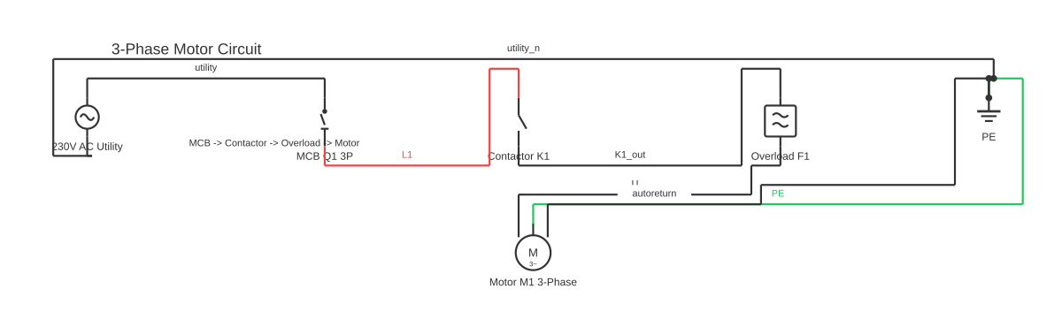
3-Phase Induction Motor Diagram
This is a free printable 3 phase induction motor diagram: download the diagram as SVG or open it and print to paper or PDF.
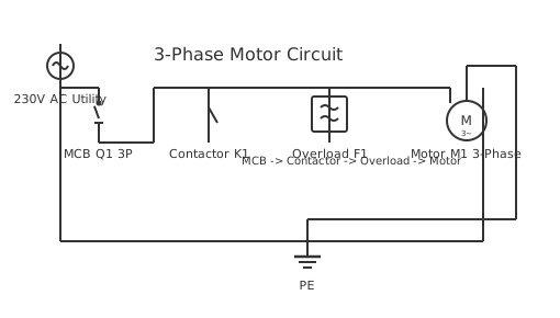
A 3-phase induction motor diagram shows how three AC supply lines connect to stator windings to produce a rotating magnetic field that drives a squirrel-cage or wound rotor without any direct electrical connection to the rotor.
A three-phase induction motor is the workhorse of industrial electrical systems. Understanding its circuit diagram requires grasping two distinct sections: the stator circuit and the rotor circuit, even though the rotor receives no wired supply.
The stator contains three sets of windings, physically displaced 120 degrees apart inside the stator core. When three-phase alternating current — typically designated L1, L2, and L3 — is applied to these windings, each phase reaches its peak voltage 120 electrical degrees after the previous one. The combined effect of these time-shifted, spatially-offset magnetic fields is a single rotating magnetic field (RMF) that sweeps around the stator bore at synchronous speed. Synchronous speed (Ns) is calculated as Ns = (120 × f) / P, where f is supply frequency in hertz and P is the number of poles.
The squirrel-cage rotor — by far the most common type — consists of aluminium or copper bars embedded in a laminated iron core, short-circuited at both ends by end rings. No external wiring connects to the rotor. Instead, the rotating magnetic field of the stator induces voltages in those bars by transformer action. The resulting circulating currents in the bars interact with the stator field to produce torque, pulling the rotor in the direction of field rotation.
The rotor never quite catches the rotating field — if it did, there would be no relative motion, no induced voltage, and no torque. This difference between synchronous speed and rotor speed is called slip (s), expressed as a percentage: s = ((Ns − Nr) / Ns) × 100. At full load, slip is typically 2–5% for standard squirrel-cage motors.
In a wiring diagram, the stator windings are shown in either star (Y) or delta (Δ) configuration. Star connection ties one end of each winding to a common neutral point; delta connects each winding end-to-end in a triangle. A star-delta (Y-Δ) starter diagram adds a contactor set that first energises the motor in star to limit inrush current, then switches to delta for full-speed running. The supply side of the diagram shows a main isolator, overload relay, and the three-phase contactor before the motor terminals U1, V1, W1 (and U2, V2, W2 for reconnection).
3-Phase Induction Motor Terminal Box: Reading U1/V1/W1 and U2/V2/W2
A standard 3-phase induction motor with IEC labelling exposes six terminals in the terminal box, arranged in two rows. The top row holds U1, V1, and W1 — the line-voltage ends of the three stator windings. The bottom row holds W2, U2, and V2 (note the order: W2 is typically at the left of the bottom row in IEC layouts). Each paired set — U1/U2, V1/V2, W1/W2 — represents one complete winding phase. Supply phases L1, L2, and L3 connect to U1, V1, and W1 respectively. NEMA-labelled motors use T1–T9 instead of the IEC U/V/W convention, but the physical arrangement of the six-terminal box follows the same logic.
Star (Y) Connection: When and How
In star connection, the three winding return ends — U2, V2, and W2 — are joined together at a single neutral point using shorting link bars or a copper bridge. The supply terminals U1/V1/W1 connect to L1/L2/L3 as normal. In star, each individual winding sees only the phase-to-neutral voltage, which is line voltage divided by the square root of 3 (approximately 58% of line voltage). On a 400V supply each coil sees about 231V. Star connection is used when the motor's nameplate shows the higher of its two rated voltages — for example, a motor rated 230/400V is connected in star on a 400V supply.
Delta (Δ) Connection: When and How
In delta connection, the three windings form a closed loop: link bars bridge U1 to W2, V1 to U2, and W1 to V2. Each winding is connected directly between two supply phases, so it sees full line-to-line voltage. On a 400V supply each coil sees 400V. Delta connection is used when the motor's nameplate shows the lower of its two rated voltages — a 230/400V motor runs in delta on a 230V supply. In a star-delta starter the motor begins in star (reduced voltage, approximately one-third of full-load starting current) and then switches to delta at running speed. This reduces inrush current and mechanical shock but also reduces starting torque by one-third, making star-delta suitable only for lightly loaded starts such as pumps, fans, and unloaded conveyors.
Reading the Nameplate: Voltage Selection
The motor nameplate shows dual voltages in the format low/high — for example 230/400V or 400/690V. The lower figure is the delta operating voltage; the higher figure is the star operating voltage. If your supply voltage matches the lower figure, connect in delta. If it matches the higher figure, connect in star. A motor rated 400/690V connected in delta on a 690V supply will be overloaded; connected in star on 400V it will be underpowered. Always match the connection to the supply voltage according to the nameplate.
A three-phase induction motor wiring diagram must show both the terminal box connections and the starter or drive arrangement. Most motors have six winding ends brought out to terminals T1–T6 (or U1, V1, W1, U2, V2, W2 in IEC notation), allowing star (Y) connection for lower starting current or delta connection for full torque. A DOL (direct-on-line) starter connects the three supply lines directly; a star-delta starter begins in star, then switches to delta after a timer. Variable-frequency drives add input and output wiring considerations along with motor cable screening requirements. Map out your complete three-phase induction motor circuit — including overload relay, contactor, and grounding — using the free online diagram editor.
How to wire 3 phase induction motor diagram
- Identify the supply voltage and motor rating Read the motor nameplate to confirm rated voltage (e.g. 400 V, 3-phase, 50 Hz), full-load current, power in kW, and connection type (Y or Δ). These values determine your cable size, overload relay setting, and starter type.
- Draw the main circuit (power circuit) Start at the top of the diagram with the three supply lines L1, L2, L3. Pass them through the main isolator, then through the normally-open contacts of the main contactor (KM1), then through the three elements of the thermal overload relay (F2), and finally to motor terminals U1, V1, W1.
- Add the stator winding connection At the motor symbol, show whether the windings are connected in star or delta. For a dual-voltage motor (e.g. 230/400 V) or a star-delta starter, indicate all six terminals and the link connections. Label internal windings clearly.
- Draw the control circuit On a separate rung (or below the main circuit), draw the 230 V or 110 V control supply. Include the stop pushbutton (normally closed), start pushbutton (normally open), the auxiliary contact of KM1 for latching (self-holding), and the coil of KM1. Connect the normally-closed auxiliary contact of the overload relay (F2) in series to interrupt control if the motor trips.
- Add protection devices Include a main circuit breaker or fuses (HRC type, sized per local code) upstream of the contactor. Add an overload relay set at 100–110% of full-load current. Earth (PE) the motor frame and show the earthing conductor on the diagram.
- Label all components with reference designators Use IEC 81346 or your project standard. Common designators: Q1 (isolator), KM1 (main contactor), F1 (fuses), F2 (overload relay), SB1 (stop button), SB2 (start button). Add cable references and terminal numbers.
- Verify rotation direction and record as-built On first power-up (by a qualified person), jog the motor briefly and confirm the shaft rotates in the intended direction. If reversed, de-energise and lock out, then swap two supply phases at the starter terminals — never at the motor itself unless access requires it.
Specifications
| Standard supply voltage (IEC) | 400 V line-to-line, 3-phase, 50 Hz (230 V line-to-neutral) |
|---|---|
| Synchronous speed formula | Ns = (120 × f) / P; e.g. 1500 rpm at 50 Hz, 4-pole |
| Typical full-load slip | 2–5% for standard squirrel-cage motors |
| Starting current (DOL) | 5–8 × full-load current (motor nameplate dependent) |
| Motor terminal designations (IEC 60034-8) | U1, V1, W1 (line ends); U2, V2, W2 (neutral/delta ends) |
| Insulation class (IEC 60085) | Class F (155 °C) most common in modern motors; Class B (130 °C) legacy |
| Efficiency classes (IEC 60034-30-1) | IE1 (standard), IE2 (high), IE3 (premium), IE4 (super premium) |
| Protection rating (IEC 60034-5) | IP55 typical for general industrial; IP23 for ventilated indoor motors |
Safety warnings
- All installation, commissioning, and maintenance work on three-phase motor circuits must be carried out by a licensed or registered electrician and must comply with the applicable wiring regulations: NEC/NFPA 70 (USA), BS 7671 (UK), AS/NZS 3000 (Australia/New Zealand), or IEC 60364 (international). Diagrams here are for reference and education only.
- Always isolate the motor supply using the main isolator or disconnect switch, apply an approved lockout-tagout (LOTO) device, and verify the circuit is dead with a calibrated voltage tester at all three phases and at the motor terminals before touching any conductors or terminals.
- Three-phase voltages (typically 380–415 V line-to-line) are lethal. Do not rely on a contactor being open as proof of isolation — contactors can fail welded. The isolator upstream of the contactor must be opened and locked.
- High starting currents (typically 5–8 times full-load current) can cause voltage dips on the supply and damage improperly sized cables or switchgear. Never increase fuse size as a substitute for correctly sized components.
- Single phasing (loss of one supply phase) will cause the motor to overheat rapidly. Ensure the thermal overload relay is correctly set and tested. Consider installing phase-failure protection relays in critical applications.
Tools needed
- Calibrated true-RMS multimeter with CAT III or CAT IV rating
- Non-contact voltage tester (NCV tester)
- Insulation resistance tester (Megger) rated for 500 V or 1000 V
- Clamp meter for measuring running and starting current
- Screwdrivers (flat and Pozidriv), torque screwdriver for terminal tightening
- Lockout-tagout (LOTO) kit with padlock and hasps
- Wire strippers and crimping tools appropriate for cable cross-section
- Phase rotation meter (phase sequence tester)
Common mistakes
- Setting the overload relay to the supply current rather than the motor full-load current printed on the nameplate — the relay should be set to nameplate FLC.
- Omitting a self-holding (latching) auxiliary contact in the control circuit, which causes the motor to stop the moment the start button is released.
- Connecting the earth (PE) conductor to the motor neutral terminal instead of the dedicated earth terminal on the frame or terminal box.
- Reversing two phases without checking the load — some driven equipment (pumps, compressors, fans) can be damaged or dangerous if run in reverse, even briefly.
- Using a single-phase overload relay on a three-phase motor, providing no protection against phase unbalance or single phasing.
- Leaving the star link installed when reconnecting a dual-voltage motor for delta operation at the higher voltage, resulting in severely reduced torque and overheating.
- Connecting a 230/400V motor in delta on a 400V supply — each winding receives 400V instead of 230V, causing immediate overheating and winding failure.
- Fitting star link bars (shorting U2/V2/W2) on the supply terminals (U1/V1/W1) instead of the return terminals — this shorts two or three supply phases together and will blow fuses or trip the breaker immediately.
- Using star-delta starting on a heavily loaded conveyor or compressor that requires high starting torque — the one-third torque reduction in star causes the motor to stall before it can switch to delta.
- Reversing the phase rotation (swapping any two supply phases L1/L2/L3 at the terminal box) without realising it — the motor will run in the wrong direction; swap any two of the three supply leads to reverse rotation.
Troubleshooting
- Motor hums but does not start and the shaft is stationary
- Cause: Single phasing — one of the three supply phases is missing or a fuse has blown on one phase; or the load is jammed or seized Fix: Isolate and lock out the supply. Use a multimeter to measure voltage across all three phases at the motor terminals. Replace blown fuse if found. Check that the shaft can be turned freely by hand before re-energising.
- Overload relay trips shortly after starting
- Cause: Relay set too low, motor running overloaded, excessive starting frequency, or beginning of winding insulation failure Fix: Confirm relay setting matches nameplate FLC. Measure running current with a clamp meter on all three phases. If current is balanced and within nameplate rating, check relay calibration. Carry out insulation resistance test on motor windings.
- Motor runs but vibrates excessively
- Cause: Phase imbalance (one phase voltage significantly lower than the others), a damaged rotor bar, or the motor is mechanically unbalanced or misaligned with its driven load Fix: Measure line voltage on all three phases under load. Phase imbalance greater than 2% causes disproportionate current imbalance. Check shaft alignment and coupling condition. Motor rewinding or replacement may be required if rotor bars are broken.
- Motor runs in the wrong direction
- Cause: Supply phase sequence is opposite to what the wiring diagram specifies Fix: De-energise, lock out, then swap any two of the three supply conductors at the starter terminals (not at the motor unless necessary). Re-energise and confirm rotation direction before reconnecting the driven load.
- Motor runs hot and insulation smells
- Cause: Overloading, blocked ventilation, incorrect voltage, high ambient temperature, or deteriorated winding insulation Fix: Measure running current on all three phases and compare to nameplate FLC. Inspect ventilation openings and cooling fan. Check supply voltage at motor terminals under load. Carry out insulation resistance test; if below 1 MΩ (at 500 V test voltage), the motor requires rewinding or replacement.
- Motor runs hot and draws excess current above nameplate FLA after installation
- Cause: Motor is connected in delta when the supply voltage matches the star rating, causing each winding to see full line-to-line voltage at roughly 1.73× its rated voltage. Fix: De-energise and isolate the motor. Open the terminal box and reconfigure the link bars from delta to star — join U2, V2, W2 together and remove the cross-phase link bars. Confirm the supply voltage matches the higher figure on the nameplate before re-energising.
- Star-delta starter changes to delta but motor stalls or trips the overload relay
- Cause: The connected load is too heavy for the reduced starting torque available in star. Star-delta starting provides only one-third of direct-on-line starting torque. Fix: Ensure the driven load (pump, fan, compressor) is unloaded or lightly loaded at startup. Increase the star-to-delta transition time on the timer relay to allow the motor to reach closer to synchronous speed before switching to delta. For high-inertia or loaded starts, consider a soft-starter or variable frequency drive instead.
Frequently asked questions
What is the difference between synchronous speed and rotor speed in an induction motor?
Synchronous speed is the speed of the stator's rotating magnetic field, determined by supply frequency and pole count. The rotor always runs slightly slower — this difference is called slip. Without slip there is no relative motion between field and rotor conductors, so no induced current and no torque. Typical full-load slip is 2–5%.
Why does a 3-phase induction motor not need brushes or a commutator?
The rotor is energised purely by electromagnetic induction from the stator field, not by a direct electrical connection. Because no current needs to be conducted into or out of a rotating shaft, there is no need for brushes, slip rings, or a commutator, which is why squirrel-cage induction motors are so robust and maintenance-light.
What happens if one phase of a 3-phase supply is lost (single phasing)?
The motor loses the balanced rotating magnetic field and attempts to continue running on the remaining two phases. This creates excessive current in the remaining stator windings, causes severe vibration and heating, and will damage or destroy the motor if the thermal overload relay does not trip the supply quickly.
What do the terminal markings U1, V1, W1, U2, V2, W2 mean on a motor terminal board?
These are the standard IEC designations for the six ends of the three stator windings. U1–U2 is the first winding, V1–V2 the second, W1–W2 the third. Star connection links U2, V2, W2 together; delta connection links U1 to W2, V1 to U2, and W1 to V2.
Can a 3-phase induction motor run in reverse?
Yes. Reversing the direction of rotation requires swapping any two of the three supply phases at the motor terminals — for example, exchanging L1 and L2. This reverses the direction of the rotating magnetic field and therefore the direction of rotor torque. A reversing starter diagram includes two contactors interlocked to prevent both closing simultaneously.
What do the terminals U1, V1, W1, U2, V2, W2 mean on a 3-phase motor?
These are IEC 60034 standard labels for the six terminals of a dual-voltage 3-phase induction motor. U1/V1/W1 are the supply ends of the three stator windings; U2/V2/W2 are the opposite (return) ends. Each pair (U1/U2, V1/V2, W1/W2) represents one complete winding phase. Supply phases L1, L2, L3 always connect to U1, V1, W1.
How do I connect the terminal box links for star vs delta?
Star: install shorting link bars across U2, V2, and W2 to join them at a common neutral point. Supply connects to U1/V1/W1. Delta: install link bars as follows — bridge U1 to W2, V1 to U2, and W1 to V2. The same three supply terminals U1/V1/W1 connect to L1/L2/L3 in both cases; only the link bar arrangement in the lower row changes.
When should I use star connection and when delta on a dual-voltage motor?
Match the connection to the supply voltage and the nameplate. A motor rated 230/400V connects in delta on a 230V supply (each winding sees 230V, which is the delta rating) or in star on a 400V supply (each winding sees 231V ÷ by √3 correction = effectively the lower winding voltage). The simple rule: star for the higher nameplate voltage, delta for the lower nameplate voltage.
How do you wire a 3-phase induction motor?
For a three-phase induction motor, connect supply lines L1, L2, L3 to the starter input terminals, then from the starter output to motor terminals T1, T2, T3 (or U1, V1, W1). In star (Y) connection, the opposite ends T4, T5, T6 (U2, V2, W2) are linked together at a common neutral point; in delta connection, T1-T6, T2-T4, and T3-T5 are paired so each winding is connected across a phase-to-phase voltage. Always include a thermal overload relay sized to the motor's full-load current between the contactor and motor terminals. The motor frame (PE terminal) must be bonded to the protective earth conductor; verify phase rotation with a rotation tester before the first start to ensure the shaft turns in the correct direction.
Related diagrams
- 230v 3 phase motor wiring diagram
- 3 phase forward reverse motor control circuit diagram
- 3 phase motor starter connection
- 3 phase motor to single phase wiring diagram
- 3 phase motor winding diagram
- 3 phase motor wiring