3 Phase Motor Wiring Diagram: Terminal Connections and Starter Circuits
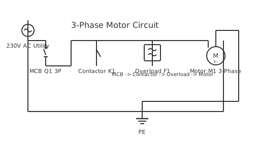
This is a free printable 3 phase motor wiring diagram: download the diagram as SVG or open it and print to paper or PDF.
A three-phase motor wiring diagram shows how to connect line conductors L1, L2 and L3 to motor terminals U1, V1 and W1 through overload and contactor protection, enabling safe and efficient motor starting and running operation.
Diagram checks and scope
- Components
- 6
- Wired connections
- 7
- Automated check
- Automated pin, route, source, and topology checks passed; this is not a safety certification.
Three-phase induction motors are the backbone of industrial drive systems, converting electrical energy to mechanical rotation through electromagnetic induction across a rotating magnetic field. The stator carries three sets of windings displaced 120 electrical degrees apart. When energised by a balanced three-phase supply, these windings create a smoothly rotating magnetic field whose speed, called synchronous speed, equals 120 times the supply frequency divided by the number of poles. A four-pole motor on 50 Hz supply rotates at 1500 RPM synchronously, with the rotor turning slightly slower — typically 1450 RPM — due to slip, which is the mechanism by which torque is produced. Correct terminal identification is essential before wiring. Standard IEC motors mark terminals U1, V1, W1 for the start of each winding and U2, V2, W2 for the end. Star connection links U2, V2 and W2 together at a neutral point, applying line-to-neutral voltage across each winding. Delta connection links U1 to W2, V1 to U2, and W1 to V2, applying full line-to-line voltage across each winding and increasing available torque at lower speeds. The wiring path from the main supply must pass through a correctly rated circuit breaker or fuse assembly that provides short-circuit protection, then through a thermal overload relay set to the motor full-load amperes, and finally through the main contactor contacts before reaching motor terminals. Contactor selection requires a current rating matched to the motor full-load amps plus an overload relay class matched to the starting time profile. Class 10 relays suit motors starting within ten seconds; Class 20 suits high-inertia loads with longer start times. Cable cross-section is selected from the applicable standard ampacity table with an additional 25 percent margin for continuous duty. Phase sequence must be verified with a phase sequence meter before energising — reversed phase sequence causes reverse rotation, which can damage driven machinery or create safety hazards. All metal enclosures, motor frames, and cable armour must be bonded to the protective earth bus with a conductor sized per the fault-clearing requirements of the overcurrent device. Megohmmeter testing of winding insulation resistance at 500 V DC before energising confirms freedom from moisture ingress or winding damage that would otherwise result in insulation failure under operating voltage.
How to wire 3 phase motor wiring diagram
- Read nameplate and plan wiring Record voltage, full-load amps, frequency, insulation class and IP rating from the motor nameplate. Confirm supply voltage matches nameplate and plan cable size, contactor rating and overload relay setting.
- Test winding insulation Apply 500 V DC between each winding pair and between each winding and frame using a megohmmeter. Record readings and confirm all exceed 1 megohm before proceeding.
- Install and wire contactor and overload Mount contactor and thermal overload relay in the enclosure. Wire L1, L2, L3 to contactor input terminals. Wire contactor output to overload relay input. Set overload relay to motor nameplate FLA.
- Configure motor terminal box Remove the terminal box cover and configure link bars for star or delta as required by nameplate voltage and supply. Torque all link bar bolts to the specified value.
- Connect supply cables to motor Run correctly sized cables from overload relay output to motor terminals U1, V1, W1. Connect protective earth to motor frame earth stud. Confirm all terminations are tight.
Specifications
| Supply voltage (typical) | 400 V AC three-phase (230/400 V or 400/690 V nameplate) |
|---|---|
| Overload relay class | Class 10 standard; Class 20 for high-inertia loads |
| Cable sizing margin | 125% of motor full-load amps for continuous duty |
| Insulation resistance minimum | 1 MΩ per kV rated voltage at 500 V DC test |
Safety warnings
- De-energise and lock out all three phases at the isolator before touching any motor terminal — residual capacitance in long cable runs can hold dangerous charge.
- Verify phase sequence with a meter before first run — reversed rotation can mechanically damage pumps, compressors and gearboxes immediately.
- Set thermal overload relay to motor nameplate full-load current before energising — incorrect setting allows winding damage from sustained overcurrent.
Tools needed
- Phase sequence meter to confirm L1-L2-L3 rotation direction before start
- Clamp-on ammeter for measuring actual running current against nameplate FLA
- Insulation resistance tester (500 V DC megohmmeter) for winding health check
- Torque screwdriver calibrated to terminal manufacturer specification
Common mistakes
- Connecting all six motor terminals to line supply without configuring star or delta links, causing winding short circuits.
- Setting the overload relay to the cable rating rather than the motor nameplate FLA, leaving windings unprotected.
- Omitting the protective earth connection to the motor frame, creating a shock hazard if winding insulation fails.
Troubleshooting
- Overload relay trips immediately on start
- Cause: Overload set too low or motor in locked-rotor condition due to mechanical jam Fix: Verify overload setting matches nameplate FLA. Check motor rotates freely by hand before energising. Increase overload class if normal starting current causes nuisance tripping.
- Motor runs hot after short time
- Cause: Single phase supply or incorrect winding connection causing unbalanced current Fix: Measure current on all three phases with a clamp meter. Balance must be within 5 percent. Identify open fuse or faulty contactor contact if one phase reads zero.
- Motor vibrates excessively
- Cause: Mechanical coupling misalignment or reversed phase sequence causing oscillating torque Fix: Check phase sequence with a meter and correct if needed. Inspect and realign mechanical coupling with a dial indicator to within 0.05 mm.
Frequently asked questions
How do I know if the motor should be wired star or delta?
Check the motor nameplate. If the nameplate shows two voltages such as 400/690 V, wire delta for the lower voltage and star for the higher. A motor rated 400 V delta draws full-line voltage across each winding. The same motor wired star on a 400 V supply sees only 231 V per winding and runs at reduced power, which is exploited during star-delta starting.
What causes a three-phase motor to hum and not start?
A single-phasing condition — one line missing due to a blown fuse or open contactor contact — leaves the motor stator with only two active phases. The rotating field collapses to a pulsating field that cannot produce net starting torque. The motor draws locked-rotor current on the remaining phases, overheating windings rapidly. The overload relay should trip within its class time.
How do I reverse a three-phase motor?
Swap any two of the three line conductors at the motor terminals or at the contactor output. Swapping L1 and L2 while leaving L3 unchanged reverses the phase sequence seen by the motor, reversing the direction of the rotating magnetic field and therefore rotor rotation. Dedicated reversing starter panels use two interlocked contactors to achieve this electrically.
What overload relay class should I use?
Class 10 is standard for most pump and fan applications where the motor accelerates to speed within ten seconds. Class 20 suits high-inertia loads such as large centrifuges, compressors, and conveyors where starting time extends to twenty seconds. Class 30 is reserved for very high-inertia loads. Selecting a higher class than necessary risks winding damage during extended stalls.
What insulation resistance should a healthy motor show?
A healthy motor measured at 500 V DC should show insulation resistance above 1 megohm per kilovolt of rated voltage, with an absolute minimum of 1 megohm. New motors typically show hundreds of megohms. A reading below 1 megohm indicates moisture contamination or winding damage and requires drying or rewinding before energising.
Sources and verification
Review status: Not independently reviewed. Automated topology checks confirm stored terminals and routes, not the correctness of manufacturer pin assignments, ratings, regional codes, or installation decisions. Verify those claims against the current primary documentation before use.
- IEC 61082-1:2014 — Rules for electrotechnical documents — International Electrotechnical Commission. Supports: General diagram, drawing, table, and reference-designation presentation conventions. Checked 2026-07-15.
Full written guides
Related diagrams
- 230v 3 phase motor wiring diagram
- 3 phase forward reverse motor control circuit diagram
- 3 phase induction motor diagram
- 3 phase motor starter connection
- 3 phase motor to single phase wiring diagram
- 3 phase motor winding diagram