5-Pin Trailer Plug Wiring Diagram
This is a free printable 5 pin trailer plug wiring diagram: download the diagram as SVG or open it and print to paper or PDF.
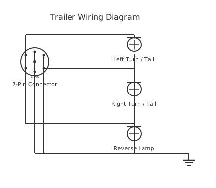
A 5-pin trailer plug wiring diagram shows how the five circuits — left turn/brake, right turn/brake, running lights, reverse light, and ground — are assigned to a round 5-pin connector used on smaller trailers, boats, and agricultural equipment.
A 5-pin round trailer connector provides the essential lighting and signal circuits needed to operate a trailer safely on public roads. It is less common than the 7-pin connectors used on most passenger vehicles in North America and Europe but is widely used on smaller utility trailers, boat trailers, and agricultural equipment — particularly where reverse lamps and electric brakes are not required.
Note on standards: a 5-pin connector is not a universal standard in the way that the 7-pin flat (common in Australia and the USA) or 7-pin round (DIN ISO 1724/11446) connectors are. The most common 5-pin round connector in North America follows an arrangement derived from the Society of Automotive Engineers (SAE) recommendations. The actual pin functions described here reflect the most widely documented 5-pin round pattern, but users should always verify against the vehicle manufacturer's documentation or the trailer manufacturer's wiring diagram before connecting.
The five circuits: 1. Ground / Earth (white wire in North American convention): the return path for all electrical circuits. Without a solid, low-resistance ground connection the trailer lights will be dim, intermittent, or non-functional. The ground wire must connect to a clean, bare-metal chassis point on both the tow vehicle and the trailer. 2. Left turn signal and brake light (yellow in North American convention): flashes when the left turn indicator is active; illuminates with brake lights. In the USA and Canada, turn and brake signals share the same lamp circuit. 3. Right turn signal and brake light (green in North American convention): same as left but for the right side. 4. Running lights / tail lights / licence (number) plate light (brown in North American convention): illuminates whenever the vehicle's parking lights, sidelights, or headlights are on. Also feeds the licence (number) plate illumination lamp. 5. Reverse light or auxiliary 12 V (blue in North American convention): typically used for a reverse (backup) lamp, or as an auxiliary power output for an electric trailer brake controller signal or other auxiliary loads on some configurations.
In some 5-pin configurations the fifth pin is used for electric brake controller output rather than a reverse lamp. Always confirm the intended use in the application.
The 7-pin trailer plug is by far the most widely used multi-function connector for trailers worldwide, but its pin assignments differ between the North American 7-pin flat (blade) and the ISO 11446 / ISO 1185 7-pin round used in Australia, New Zealand, the UK, and Europe. Utility trailers in the US most commonly use the flat 7-pin; in the UK and Australia the round 7-pin is standard. The truck-side (vehicle socket) layout mirrors the trailer-side plug, and these two differ further by country.
How to wire 5 pin trailer plug wiring diagram
- Identify the connector type and verify pin assignment Confirm you have a genuine 5-pin round connector and verify the pin numbering or colour assignment against the tow vehicle's wiring guide or the trailer manufacturer's documentation. Pin numbering on 5-pin round connectors can vary — never assume a universal layout.
- Disconnect the vehicle battery negative terminal Before making any trailer wiring connections to the vehicle harness or wiring adapter, disconnect the negative battery terminal to prevent accidental short circuits or blown fuses in the tow vehicle's trailer wiring circuit.
- Prepare the trailer wiring harness Run the trailer's wiring harness from each lamp position (rear lights, brake lights, licence plate light, reverse light) to the front of the trailer where the plug connector will be fitted. Use wire of adequate gauge for each function — 14 AWG (2.0 mm²) is sufficient for lighting; the ground wire should be the same gauge or heavier.
- Connect the ground wire first Connect the white ground wire to a clean, bare-metal point on the trailer's A-frame or draw-bar near the connector. Remove paint and corrosion with a wire brush. Use a ring terminal and bolt. Verify continuity from this point to all lamp bodies on the trailer — every lamp must share a common good earth to the chassis.
- Connect signal, running, and auxiliary wires Connect yellow to left tail/brake lamp, green to right tail/brake lamp, and brown to all running lights (tail lamps, side marker lamps, licence plate lamp). Connect blue to the reverse lamp or leave capped if not used. Use weatherproof insulated connectors or solder and heat-shrink joints — exposed connections corrode rapidly in outdoor and marine environments.
- Fit the connector plug Thread the harness wires into the 5-pin plug body, connect to the correct pins per the colour code, and tighten the cable gland. If the plug has a cover or protective cap, fit it when the trailer is unhooked to keep moisture out of the connector.
- Test all circuits before road use Reconnect the battery, plug the trailer connector into the vehicle socket, and with a helper or a trailer light tester, verify: both brake lights illuminate when the brake pedal is pressed; left and right turn signals flash correctly; running lights illuminate when parking lights are on; reverse lamp illuminates when reverse gear is selected. Correct any fault before towing on public roads.
Specifications
| Connector type | 5-pin round (various regional standards; verify manufacturer specification) |
|---|---|
| Operating voltage | 12 V DC (nominal automotive; 10–14.8 V operating range) |
| Pin 1 (White) | Ground / chassis earth |
| Pin 2 (Yellow) | Left stop / left turn signal |
| Pin 3 (Green) | Right stop / right turn signal |
| Pin 4 (Brown) | Running lights (tail / side / licence plate) |
| Pin 5 (Blue) | Reverse lamp or auxiliary 12 V |
| Maximum current per pin (typical connector rating) | 12–15 A per pin |
Safety warnings
- Trailer lighting must be functional before any towing on a public road — faulty or absent stop lights, turn signals, or tail lights are a legal offence in all jurisdictions and a serious road safety hazard. Test all circuits before every tow, particularly after extended storage or in wet or corrosive environments.
- Never bypass or omit the ground wire. A floating or high-resistance ground causes phantom signals between circuits — for example, the left turn lamp may flash when the right indicator is active, confusing other road users and creating a collision risk.
- Ensure the connector and all wiring joints are weatherproofed with appropriate connectors, heat-shrink, or waterproof self-amalgamating tape. Marine and boat trailers are especially susceptible to corrosion-related lighting failures from salt-water immersion.
- Do not overload the auxiliary (blue) pin with accessories beyond the current capacity of the trailer socket fuse and wiring. Overloaded circuits can blow the tow vehicle's trailer fuse, causing complete lighting failure while towing.
- Check local legislation for trailer lighting requirements before wiring. Some countries require amber side marker lamps, reflectors, overrun indicators, or other additional circuits not provided by a basic 5-pin connector.
Tools needed
- Digital multimeter or trailer light tester (verify correct lamp operation per circuit)
- Wire strippers and crimping tool
- Heat-shrink tubing and heat gun (weatherproof joints)
- Electrical contact cleaner (connector and earth point preparation)
- Wire brush or sandpaper (cleaning earth bonding points to bare metal)
- Insulated screwdrivers
- Self-amalgamating tape (additional weatherproofing for connector and exposed joints)
Common mistakes
- Poor ground connection: the most frequent cause of trailer lighting faults; clean the connection to bare metal and verify continuity throughout the trailer chassis.
- Using the wrong colour code: 5-pin connectors do not have a single international standard; always verify pin assignments for your specific connector and vehicle before wiring.
- Not testing stop lights independently from turn signals: the shared stop/turn circuit can appear to work when tested with the turn signal but fail under brake activation if the vehicle's brake light feed is not correctly wired to the socket.
- Using under-rated or non-marine-grade wire: standard automotive wire corrodes rapidly in wet and salt environments; use tinned copper wire for boat trailers.
- Omitting the dust/protective cap when the trailer is unhitched: exposed socket pins corrode, causing contact resistance and intermittent faults — always refit the cap.
- Running trailer wiring across sharp metal edges without protection: vibration causes chafing through insulation over time; use grommets and cable clips to route and secure wiring.
Troubleshooting
- All trailer lights fail to operate
- Cause: Blown fuse in the tow vehicle's trailer circuit, faulty or corroded connector, or an open-circuit ground connection Fix: Check the tow vehicle's trailer lighting fuse first. Inspect the 5-pin connector for bent or corroded pins. Measure ground continuity from the trailer chassis to the vehicle chassis through the connector. Replace any blown fuse with the correct rating — never a higher rating.
- Left and right turn signals flash on the wrong side
- Cause: Yellow and green wires reversed at the plug or socket, or cross-connected at a lamp body Fix: Isolate the supply, remove the plug from the socket, and verify yellow connects to the left lamp and green to the right lamp throughout the harness. Correct any crossed connections.
- Running lights work but stop and turn signals do not
- Cause: Open circuit or bad connection in the yellow and/or green wires, or a failed tow vehicle trailer light relay Fix: Check voltage at the yellow and green pins of the vehicle socket when indicators and brakes are activated. If voltage is present at the socket but absent at the trailer lamp, trace the trailer harness for breaks. If voltage is absent at the socket, fault the vehicle's trailer wiring circuit.
- Lamps illuminate continuously when not commanded
- Cause: Short circuit between wires, typically from chafed insulation — a live wire shorting to the running-light or turn-signal circuit Fix: Unplug the trailer. Inspect the harness for chafed or bare wires, particularly where cables pass through or around metal edges. Repair insulation and re-route with grommets and clips.
Frequently asked questions
What is the wiring colour code for a 5-pin round trailer plug?
In North American practice: white = ground; yellow = left turn/brake; green = right turn/brake; brown = running lights (tail/side/plate); blue = reverse lamp or auxiliary. These colours are widely followed but not universally mandated — always verify against the specific vehicle or trailer wiring diagram before connecting, as variations exist.
What is the difference between a 5-pin and a 7-pin trailer plug?
A 5-pin connector provides the five basic circuits: ground, left turn/brake, right turn/brake, running lights, and one auxiliary (reverse or brake controller). A 7-pin connector adds two more circuits — typically a dedicated electric brake output and a 12 V auxiliary power circuit — enabling electric brakes and powered accessories on larger trailers such as caravans.
Why are my trailer lights dim even though all wires are connected?
Dim lights are almost always caused by a high-resistance ground connection. Trailer lighting circuits operate at low current, and even a few ohms of resistance in the ground path significantly reduces voltage at the lamps. Clean the ground connection at both ends to bare metal, check the ground wire for corrosion or breaks, and verify the trailer's chassis provides a continuous earth path to every lamp.
Do the left turn and brake light share the same wire on a 5-pin trailer plug?
Yes. In North American SAE-style trailer wiring, turn signals and brake lights share the same lamp and circuit wire on each side. This is called a two-wire system (combined function). European trailers typically use a three-wire system where turn signals and brake lights are on separate wires and separate lamp elements, which is why European 7-pin connectors have a distinct brake lamp pin.
Can I use a 5-pin trailer plug for a caravan with electric brakes?
A 5-pin connector is marginal for a caravan with electric brakes. The blue (auxiliary) pin can be used for a brake controller signal in some arrangements, but a caravan also typically requires a 12 V auxiliary power supply and potentially a battery charging line — circuits that require additional pins. A 7-pin flat or 7-pin round connector is standard and strongly recommended for caravans and large trailers.
What is the wiring diagram for a 7-pin trailer plug?
On a North American 7-pin flat connector the standard SAE colour/function assignment is: white = ground, yellow = left turn/brake, green = right turn/brake, brown = tail/running lights, blue = electric brakes, red = 12 V auxiliary power, and black = reverse lights (or 12 V battery charge on some layouts). Always confirm with the trailer manufacturer, as colour coding is not universally consistent across brands.
What is the wiring diagram for a 7-pin utility trailer plug?
A basic utility trailer typically only uses 4 of the 7 available pins: ground (white), left turn/brake (yellow), right turn/brake (green), and tail lights (brown). The remaining pins (blue for electric brakes, red for 12 V aux, black for reverse) are wired only if the trailer is equipped with those features. The 7-pin connector is used even on simple utility trailers to remain compatible with vehicles that have a 7-pin socket.
What is the 7-pin trailer plug wiring diagram in Australia?
Australia uses the ISO 1185 7-pin round connector. The Australian standard colour coding is: pin 1 (yellow) = left indicators, pin 2 (blue) = reversing lamp, pin 3 (white) = earth/ground, pin 4 (green) = right indicators, pin 5 (brown) = right tail and side markers, pin 6 (red) = brake/stop lamps, pin 7 (black) = left tail and side markers. This differs from the North American flat 7-pin, so an adapter is required between the two standards.
What is the 7-pin trailer plug wiring diagram on the truck side?
The truck-side (tow vehicle) socket mirrors the trailer-side plug in pin layout but is wired to the vehicle's electrical circuits. For a North American flat 7-pin socket: ground connects to chassis, yellow and green tap into the respective turn/brake signal wires, brown taps the tail lamp circuit, blue connects to the electric brake controller output, and red to a fused battery or ignition feed. The socket is usually the female connector on the vehicle.
What is the 7-pin trailer plug wiring diagram in the UK?
The UK uses two 7-pin ISO standards: ISO 1185 (12N, black connector) for standard lighting, and ISO 3731 (12S, grey connector) for supplementary services. On the 12N connector: pin 1 = left indicators (yellow), pin 2 = rear fog lamp (blue), pin 3 = earth (white), pin 4 = right indicators (green), pin 5 = right tail (brown), pin 6 = brake/stop (red), pin 7 = left tail (black). Modern UK towing vehicles often use a single 13-pin ISO 11446 connector which combines both functions.
Related diagrams
- 12 pin trailer plug wiring
- 13 pin trailer plug wiring diagram
- 4 pin 5 wire trailer wiring diagram
- 5 pin plug wiring diagram
- 5 pin trailer wiring diagram
- 5 pin trailer wiring diagram with brakes