6-Way Trailer Plug Wiring Diagram
This is a free printable 6 way trailer plug diagram: download the diagram as SVG or open it and print to paper or PDF.
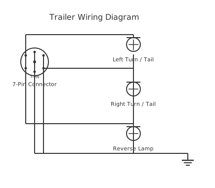
Map every pin of a 6-way round trailer plug to its function — brake controller, electric brakes, tail, stop, reverse, and auxiliary — before you splice a single wire.
The 6-way round connector is one of the most common trailer electrical interfaces in North America, used extensively on horse floats, stock trailers, boat trailers with electric brakes, and utility trailers requiring a dedicated brake controller output. It is distinct from the flat 6-way connector found on lighter-duty applications. The round 6-way adds brake controller output and an auxiliary circuit compared to the flat 4-way, making it the minimum viable connector for trailers with electric drum brakes.
Pin assignments follow a widely adopted convention in the US and Australian markets, though slight variations exist between manufacturers. The most common layout assigns: pin 1 — electric brakes (blue wire, brake controller output); pin 2 — tail/running lights (brown wire); pin 3 — ground/earth return (white wire); pin 4 — left turn and stop (yellow wire); pin 5 — right turn and stop (green wire); pin 6 — auxiliary or reverse lights (red wire). The ground pin is the most critical — a corroded or undersized ground causes partial or complete lighting failure and inconsistent brake operation, and is the single most common source of trailer electrical faults.
The electric brake pin (blue) carries the brake controller output signal, which ranges from approximately 0 V (no braking) to 12 V (maximum braking demand). This is a modulated output from the brake controller, not a direct battery feed. Current through this circuit depends on the number of brake magnets: each electric brake magnet draws roughly 3 A, so a two-axle trailer with four brakes draws approximately 12 A. Size the wiring and connector accordingly.
The auxiliary circuit (red, pin 6) can be configured for reverse lights, 12 V trailer battery charging, interior lighting, or a winch power feed, depending on the application. This circuit should be independently fused at the tow vehicle.
Corrosion is the primary failure mode. Submerging the connector when launching a boat trailer without rinsing and re-greasing the connector pins will cause intermittent faults within one or two seasons.
A trailer plug wiring diagram for the 7-way RV blade connector covers the seven pins that handle running lights (brown), left turn/brake (yellow), right turn/brake (green), ground (white), 12 V battery charge (blue centre pin), electric brakes (blue outer), and reverse/auxiliary (black). This round 7-blade plug is the North American standard for most full-size trailers with electric brakes and is distinct from the 6-way round connector used on older trailers and horse trailers. Knowing which pin serves which function prevents blown tow-vehicle fuses and non-functional brake controllers. Use the free browser-based editor to map out and label your trailer plug wiring diagram.
How to wire 6 way trailer plug diagram
- Identify connector type and inspect for damage Confirm you have a 6-way round connector (circular housing, six pins in a ring pattern with one centre pin on some variants). Inspect pins for corrosion, bent pins, or cracked housing. A corroded socket on the tow vehicle is the most common source of faults on otherwise correctly wired trailers.
- Map the pin positions using a reference diagram Orient the connector with the latch or key slot at the top. Number the pins using your reference diagram. In the most common convention: pin 1 (top) = brakes (blue); working clockwise: pin 2 = ground (white), pin 3 = left turn/stop (yellow), pin 4 = right turn/stop (green), pin 5 = tail lights (brown), pin 6 = auxiliary (red). Verify against your vehicle's or trailer manufacturer's documentation before cutting wires.
- Test tow vehicle socket with a circuit tester Use a 12 V circuit tester or multimeter. With the ignition on and trailer disconnected, probe each pin against the ground pin: activate left indicators, right indicators, brakes, and running lights in sequence, confirming which pin activates. This verifies the vehicle socket before assuming the trailer wiring is the fault.
- Connect trailer wiring to socket body Strip wire ends 8 mm. Insert into the correct terminal positions per your verified pin map. Use the socket manufacturer's method: screw terminals require tinned wire ends; crimp-terminal sockets require appropriate-sized crimp ferrules. Pull-test each wire after securing to confirm it cannot be withdrawn.
- Apply dielectric grease and reassemble Apply a thin coat of dielectric (non-conductive) grease to all pin faces and the socket cavity before mating the plug. This displaces moisture and prevents the pin-to-socket micro-corrosion that causes intermittent faults. Do not use petroleum-based grease, which can swell rubber seals.
- Function-test all circuits Connect the trailer, activate each function in sequence, and confirm operation at each trailer light and brake assembly. Use a voltmeter at the brake magnet terminals to confirm brake controller output ramps from 0 V to approximately 12 V when the brake pedal is depressed.
Specifications
| Connector type | 6-way round, standard convention |
|---|---|
| Pin 1 function | Electric brakes (blue wire, brake controller output) |
| Pin 2/Ground function | Common ground/earth return (white wire) |
| Tail/running lights pin | Brown wire |
| Left turn and stop | Yellow wire |
| Right turn and stop | Green wire |
| Auxiliary/reverse | Red wire |
| Maximum connector current rating | 30 A (connector body); individual circuit fuse protection required |
Safety warnings
- Always disconnect the trailer from the tow vehicle and isolate the vehicle battery before cutting or splicing wiring in the trailer harness to prevent accidental brake controller activation or short circuits.
- The electric brake circuit carries up to 12–15 A under full braking demand. Undersized wiring will overheat and can cause a fire in the harness conduit. Size wiring for the actual brake magnet load.
- This diagram is a general reference only. Pin assignments vary between manufacturers and regions. Always verify against the connector manufacturer's specification and the vehicle's wiring diagram before making connections.
- Ensure all connections in the trailer harness are weatherproofed with heat-shrink adhesive-lined tubing or equivalent — exposed butt splices corrode rapidly when the trailer is used near water or in wet conditions.
- Never operate a trailer with electric brakes without a functioning brake controller installed and calibrated in the tow vehicle. Uncalibrated or absent brake controllers are a road safety hazard.
Tools needed
- Digital multimeter
- 12 V circuit tester / test light
- Wire strippers and crimping tool
- Heat gun (for adhesive-lined heat-shrink)
- Screwdrivers (flathead and Phillips)
- Dielectric grease applicator
- Cable ties and conduit (for harness routing)
Common mistakes
- Assuming pin numbering is consistent across all 6-way round connector brands — always verify with a circuit tester before committing wire colours to positions.
- Using the trailer frame as the only ground path without running a dedicated ground wire back to the socket — frame corrosion creates a high-resistance ground that causes all trailer electrical symptoms simultaneously.
- Omitting a fuse on the auxiliary circuit, resulting in an unprotected wire run capable of starting a fire if the insulation is chafed against the trailer frame.
- Not applying dielectric grease to the connector, leading to pin corrosion and intermittent faults within the first season of use, particularly on boat trailers.
- Joining wires with un-insulated twist-and-tape splices inside the socket body, which loosen with trailer vibration and corrode rapidly.
Troubleshooting
- All trailer lights inoperative
- Cause: Open-circuit ground (white wire) or blown fuse on vehicle socket feed Fix: Measure resistance from trailer socket ground pin to trailer chassis — should be under 0.5 Ω. Test for supply voltage at the running light pin with the vehicle lights on. Replace blown fuse if found; repair ground connection if resistance is elevated.
- Electric brakes not engaging
- Cause: No output from brake controller, open-circuit blue wire, corroded brake pin, or failed brake magnets Fix: Verify brake controller is powered and calibrated. Measure voltage at the vehicle socket brake pin during brake application — expect 0–12 V modulated output. Trace the blue wire to each brake magnet and verify continuity. Measure magnet resistance (typically 3–4 Ω per magnet) with trailer disconnected.
- One side of lights not working
- Cause: Corroded or open-circuit pin for left or right turn/stop circuit Fix: Probe the affected side's pin at the socket with the circuit active. Voltage present at socket but not at trailer light indicates a break in the trailer harness. No voltage at socket indicates a fault upstream in the vehicle tow harness or indicator relay.
Frequently asked questions
What is the difference between a 6-way round and a 6-way flat trailer connector?
The 6-way round uses circular pin arrangement and is rated for higher current, making it suitable for electric brakes and heavy auxiliary loads. The 6-way flat is a lower-profile connector more commonly used on light utility trailers. Pin assignments and wire colours differ between the two types — do not assume they are interchangeable.
Which pin carries the electric brake controller output?
In the most common North American convention, pin 1 (blue wire) carries the brake controller output. This is a modulated 0–12 V signal from the brake controller, not a direct battery connection. Each electric brake magnet draws approximately 3 A; wire and fuse the circuit for the total number of brake magnets on the trailer.
Why do my trailer lights work intermittently even with new bulbs?
Intermittent lighting is almost always a grounding problem. Measure resistance from the trailer's ground pin back to each light assembly's earth point. Any reading above 0.5 Ω will cause noticeable light dimming or flickering. Clean all ground connections at the socket body, trailer frame, and tow-ball mounting point.
Can I use the auxiliary pin (pin 6) to charge a trailer battery?
Yes, but only with proper precautions. The tow vehicle's alternator may not be sized to charge both vehicle and trailer batteries simultaneously. Use a voltage-sensitive relay (VSR) or DC-DC charger on the trailer to manage the charging process and prevent draining the tow vehicle's battery when parked with accessories running.
What wire gauge should I use for the electric brake circuit?
For a single-axle trailer (two brakes, approximately 6 A), 1.5 mm² (14 AWG) wire is typically adequate. For a tandem-axle trailer (four brakes, approximately 12 A), use 2.5 mm² (12 AWG) minimum. Always fuse the circuit at the tow vehicle at 115–125% of maximum expected current draw.
What is the wiring diagram for a 7-way trailer plug?
On a standard SAE 7-way RV blade connector: pin 1 (12 o'clock, centre) — 12 V battery charge; pin 2 — electric brakes (blue); pin 3 — tail/running lights (brown); pin 4 — left stop/turn (yellow); pin 5 — right stop/turn (green); pin 6 — ground (white); pin 7 — reverse/auxiliary (black). Confirm the vehicle-side pinout against the tow vehicle's manual because some manufacturers swap the brake and aux pins. Always clean the connector contacts to prevent voltage drop to the brake controller.
Related diagrams
- 4 way trailer plug
- 6 pin trailer plug wiring diagram
- 6 way trailer wiring diagram
- 12 pin trailer plug wiring
- 13 pin trailer plug wiring diagram
- 4 prong trailer plug wiring diagram