6-Pin Trailer Plug Wiring Diagram
This is a free printable 6 pin trailer plug wiring diagram: download the diagram as SVG or open it and print to paper or PDF.
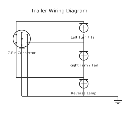
Wire a 6-pin trailer plug correctly with pinouts for electric brakes and auxiliary 12V power, including colour codes, fusing requirements, and testing procedures for safe towing.
A 6-pin trailer connector extends the basic lighting functions of a 4-pin flat connector by adding two additional circuits that are essential for trailers requiring electric brakes and a constant 12 V auxiliary power feed. This makes the 6-pin connector the standard choice for caravans, horse floats, boat trailers with electric winches, and any trailer with battery charging requirements.
The most widely used 6-pin flat connector configuration in Australia, New Zealand, and many other markets uses the following circuit allocation across six pins arranged in a flat housing:
- Pin 1: Left turn signal / tail left (typically Yellow) - Pin 2: Auxiliary / reverse lights or second function (typically Blue — in many caravanning applications, this is the electric brake output) - Pin 3: Earth / ground (typically White) - Pin 4: Right turn signal / tail right (typically Green) - Pin 5: Tail lights and clearance lamps (typically Brown) - Pin 6: Auxiliary 12 V constant power (typically Black or Red)
Note: Pin assignments and colour codes vary by regional standard and country. The Australian Standard AS 4735 defines one arrangement; other markets use different configurations. Always verify against the specific socket standard and country before wiring. Never assume colour codes are universal.
The electric brake circuit (typically Pin 2 or the Blue wire in Australian configurations) carries pulsed current from the tow vehicle's electric brake controller to the trailer's brake magnets. Each electric brake magnet draws approximately 2.5–3.5 A, so a dual-axle trailer with four brakes draws 10–14 A at maximum brake application. The brake output wire and socket contact must be rated for this current.
The 12 V auxiliary supply (Pin 6) provides a constant battery feed for charging the caravan's house battery via a battery-to-battery charger or DC-DC converter, powering breakaway safety batteries, or running trailer accessories. This circuit must be separately fused at the tow vehicle to protect the supply wiring. A 20 A fuse is typical for battery charging applications, but the actual rating depends on the connected load.
All trailer lighting circuits share a common ground (earth) pin. The quality of this earth connection is critical: a poor earth causes all lighting to be unreliable, dimly lit, or to show phantom lamp fault warnings in modern tow vehicles with LED-compatible lamp monitoring systems.
How to wire 6 pin trailer plug wiring diagram
- Identify the correct standard for your region Before buying a connector, determine which standard applies in your country. In Australia and New Zealand, the predominant standard is AS 4735 (6-pin flat). In Europe, ISO 1185 (7-pin round) is common. North America uses SAE J1239 flat connectors. Buy a connector that matches the standard used in your market to ensure compatibility with rental trailers, service facilities, and road-legal requirements.
- Test the tow vehicle socket with a multimeter Before connecting the trailer harness, verify the function of each pin on the vehicle socket using a multimeter set to DC voltage. With the ignition on and trailer connected (or use a socket tester with indicator lights), activate each function: left turn, right turn, brake lights, tail lights, hazards. Record which pin carries which function. This prevents wiring the trailer backwards to the vehicle's assignment.
- Select appropriate wire gauge for each circuit Lighting circuits (indicators, tail lights): 1.0 mm² (17 AWG) is typically adequate for LED lighting at low current. Electric brake circuit: use at minimum 2.5 mm² (13 AWG) for dual-axle applications drawing up to 14 A. 12 V auxiliary/battery charging: use 4 mm² (11 AWG) or greater depending on charger current rating and cable run length. Undersized wire overheats and causes voltage drop that dims lights and reduces brake force.
- Wire the trailer harness from the connector to the rear of the trailer Route the trailer harness from the plug forward along the drawbar and then along the trailer frame to the rear lighting clusters. Use cable ties to secure the harness at regular intervals — allowing a small loop at each point to prevent stress during articulation. Protect any sections routed through metalwork with split-loom conduit or grommet-protected holes. Keep the harness away from heat sources (exhaust, brake drums) and moving parts.
- Connect and weatherproof the plug terminals Use the correct terminals (flat or ring, as required by the connector type) and a ratchet crimp tool — not pliers. After crimping, apply dielectric grease to each terminal before insertion into the plug body to prevent corrosion. Ensure the plug cover or shell clamps securely onto the cable outer sheath to provide strain relief and weatherproofing at the cable entry.
- Test all functions systematically before coupling trailer Plug the connector into the vehicle socket. Test each function in sequence: left indicator, right indicator, brake lights (depress brake pedal), tail lights (parking lights on), hazard lights, and trailer brake activation (if fitted). For the 12 V auxiliary pin, measure output voltage with a multimeter — it should be within 0.5 V of battery voltage. If a circuit does not work, isolate and repair before towing.
Specifications
| Connector type (Australia/NZ) | 6-pin flat, per AS 4735 |
|---|---|
| Lighting circuit wire gauge (LED) | 1.0 mm² (17 AWG) minimum |
| Electric brake circuit wire gauge (dual-axle) | 2.5 mm² (13 AWG) minimum |
| Typical brake magnet current (per magnet) | 2.5–3.5 A at 12 V |
| 12V auxiliary circuit wire gauge (battery charging) | 4 mm² (11 AWG) or greater |
| Auxiliary circuit fuse (typical battery charging) | 15–30 A (size per connected load) |
| Maximum allowable voltage drop (lighting circuit) | 0.5 V from vehicle battery to lamp |
| Connector IP rating (minimum recommended) | IP54 (splash-proof and dust-protected) |
Safety warnings
- All trailer wiring must comply with the road traffic and vehicle standards regulations applicable in your country. Incorrect or non-compliant trailer lighting is a legal offence and creates serious road safety hazards for other road users.
- The electric brake circuit must be connected only to a compatible electric brake controller installed in the tow vehicle. Connecting the brake pin to any other supply (e.g., a constant 12 V) will damage the brake magnets or prevent the safety breakaway system from functioning correctly.
- Always install a fuse in the 12 V auxiliary supply circuit as close as possible to the tow vehicle battery. An unfused high-current cable running the length of the vehicle and trailer is a fire hazard in the event of a short circuit.
- Do not tow a trailer without first confirming that all lighting functions correctly. Failed stop lights, turn signals, or brake lights are illegal and create severe accident risk for following traffic.
- Ensure the trailer's breakaway safety system (where fitted) is correctly connected and tested before every tow. The breakaway battery must be charged, and the safety pin must be connected to the tow vehicle so the brakes apply automatically if the trailer separates.
Tools needed
- Digital multimeter (voltage and continuity testing)
- Ratchet crimp tool for the terminal type used
- Wire strippers
- Heat gun (for heat-shrink insulation)
- Socket tester with indicator lights (for rapid pin function verification)
- Cable ties and split-loom conduit
- Dielectric grease applicator
Common mistakes
- Assuming wire colours match a standard diagram without testing — colour codes vary significantly between manufacturers and countries, leading to crossed circuits.
- Using an undersized earth wire that cannot carry return current for all lighting circuits, causing dim lights and phantom fault warnings in the tow vehicle.
- Not applying dielectric grease to terminals, causing rapid corrosion in outdoor environments that leads to intermittent lighting and high-resistance connections.
- Installing the auxiliary circuit fuse at the trailer plug rather than at the supply source, leaving the full supply cable run unprotected in the event of a fault.
- Routing the wiring harness without allowing slack loops at articulation points, causing the harness to stretch and break wires on turns or over uneven terrain.
- Connecting the electric brake pin to the trailer's taillights or indicators instead of the brake controller output — this applies full battery voltage to brake magnets continuously and destroys them.
Troubleshooting
- All trailer lights not working on one side
- Cause: Open circuit on that signal wire, or a blown lamp plus a shared-earth fault causing backfeed Fix: Test voltage at the relevant pin on the vehicle socket: if voltage is present at the socket but not at the trailer-side lamp terminals, the fault is in the trailer harness — trace with a multimeter. If no voltage at the socket pin, the fault is in the vehicle wiring or ECU.
- Electric brake controller shows 'no trailer' or brake circuit fault
- Cause: Open circuit in brake wiring, disconnected brake magnet, or corroded pin on the trailer plug Fix: Measure resistance across the brake pin and the earth pin at the trailer plug: for a dual-axle trailer with four magnets in parallel, resistance should be approximately 1.5–2.5 Ω. If open circuit (OL), trace the brake circuit with a continuity tester. Clean the plug pin contacts and earth connection.
- 12V auxiliary pin shows correct voltage at socket but not at trailer battery connector
- Cause: High resistance or open circuit in the auxiliary cable run, blown auxiliary fuse, or corroded connector Fix: Test continuity of the auxiliary cable from plug to trailer terminal. Check the inline fuse on the auxiliary circuit. Measure voltage drop under load: apply a known load (e.g., a 10 W lamp) and measure voltage at both ends of the circuit — drop exceeding 0.5 V indicates a high-resistance connection.
Frequently asked questions
What is the difference between a 4-pin, 5-pin, and 6-pin trailer connector?
A 4-pin flat connector provides the four basic lighting circuits: left signal, right signal, tail/running lights, and ground. A 5-pin connector adds one additional circuit — typically electric brakes or auxiliary 12 V. A 6-pin connector provides all four lighting circuits plus electric brakes AND an auxiliary 12 V supply, making it suitable for caravans and trailers requiring both brake control and battery charging.
Are the pin colours and assignments universal on 6-pin connectors?
No. Pin assignments and wire colour codes vary significantly between countries and standards. Australian Standard AS 4735, European EN standards, and North American SAE J1239 each define different arrangements. Always identify pin function by testing with a multimeter on the vehicle socket rather than assuming colour codes match a wiring diagram from a different region.
How do I know if my tow vehicle has an electric brake controller output?
Check the vehicle owner's manual or the 7-pin or 6-pin socket wiring. On most factory-fitted towing packages, the brake output (typically the blue wire) will be present at the socket but only active when a compatible electric brake controller is fitted and activated. If no brake controller is installed, the brake output pin will show 0 V regardless of brake pedal application.
Why do my trailer lights work intermittently even though all bulbs are good?
Intermittent lighting is almost always caused by a poor earth (ground) connection. The single earth pin and its corresponding wire carry the return current for every lighting circuit on the trailer. A loose, corroded, or under-rated earth connection causes all lighting to be unreliable, particularly at low temperatures or after trailer washing when oxidation on the earth pin worsens.
What fuse should I use for the 12V auxiliary supply pin?
Size the fuse for the 12 V auxiliary circuit based on the actual load connected. For battery charging via a DC-DC converter: check the charger's input current rating and fuse accordingly — typically 15–30 A for a 20–40 A charger. Install the fuse as close as possible to the tow vehicle's battery, not at the socket end, so the full supply cable length is protected.
Related diagrams
- 12 pin trailer plug wiring
- 13 pin trailer plug wiring diagram
- 5 pin trailer plug wiring diagram
- 6 pin trailer wiring diagram
- 6 pin trailer wiring diagram with brakes
- 6 way trailer plug diagram