7-Pin Plug Wiring Diagram: Trailer Connector Circuits Explained
This is a free printable 7 pin plug wiring: download the diagram as SVG or open it and print to paper or PDF.
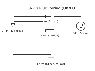
A 7-pin trailer plug wiring diagram shows each pin's assigned circuit — running lights, brake lights, indicators, reverse, and auxiliary power — for safe towing connections.
The 7-pin trailer connector is the standard electrical interface between a tow vehicle and a trailer, caravan, or horse float. Two widely used standards exist and are NOT interchangeable: the round SAE J560 connector (prevalent in North America) and the flat 7-pin connector defined by ISO 11446 / ISO 1185 combined with regional standards used across Europe, Australia, and much of the rest of the world.
The North American SAE J560 is a round 7-blade connector. Its pin assignments are: pin 1 (GND — chassis ground, white wire), pin 2 (electric brake output, blue), pin 3 (tail/running lights, brown), pin 4 (right turn/brake, green), pin 5 (left turn/brake, yellow), pin 6 (reverse lights, purple/orange, not always used), and pin 7 (12 V auxiliary/battery charge, black). Wire colours are defined by SAE J560 and are widely followed but not always consistent between manufacturers.
The European/Australian flat 7-pin connector (sometimes called the 'flat 7') uses a different layout defined by regional standards (AS 4735 in Australia; ISO 11446 in Europe). Pin assignments vary between the 12S and 12N ISO connector types used in Europe versus the flat Australian format — always verify against the relevant standard for your region.
For any towing application, each circuit should be protected by an individual fuse in the tow vehicle. Running light circuits are typically 5–10 A fused; brake outputs and auxiliary feeds are fused separately. The auxiliary pin (12 V feed) is designed for battery maintenance charging only — it must be protected by a fuse rated for the wire gauge, not used as a general-purpose power supply without appropriate overcurrent protection.
This diagram is a generic illustrative reference. Always verify pin assignments against the specific standard applicable to your region and vehicle before connecting a trailer.
How to wire 7 pin plug wiring
- Confirm the applicable connector standard for your region Before purchasing a replacement plug or socket, verify whether your vehicle and trailer use SAE J560 (round, North America), ISO/flat 7-pin (Europe), or the Australian flat 7-pin. Physical incompatibility cannot be overcome by wiring changes alone.
- Identify each circuit at the vehicle socket With the trailer disconnected and ignition on, use a test light or multimeter to probe each pin of the tow vehicle socket. Operate indicator stalks, brake pedal, headlights, and reverse to identify which pin activates for each function. Record your findings before proceeding.
- Prepare the trailer plug wiring Strip wire ends to approximately 8 mm. Use appropriately rated automotive-grade wire for each circuit. Crimp insulated terminals for each connection; avoid bare twisted joints exposed to weather.
- Connect wires to the correct plug terminals Following the identified pin functions and your regional standard, terminate each wire to the correct pin. Ensure the ground wire makes solid contact with the plug's earth terminal — a poor ground is the single most common cause of trailer lighting faults.
- Secure and weatherproof the connector body Reassemble the plug shell tightly. Apply dielectric grease to the contacts to prevent corrosion from road moisture. If the connector will be exposed to submersion (e.g., boat trailers), use a fully sealed waterproof connector.
- Test all circuits before towing Connect the plug to the tow vehicle socket and verify every function: left indicator, right indicator, brake lights, running lights, reverse lights (if wired), and auxiliary voltage. Use a trailer tester tool if available to check all pins simultaneously.
Specifications
| Standard (North America) | SAE J560 — 7-blade round connector, 12 V DC |
|---|---|
| Standard (Europe) | ISO 11446 (12S) and ISO 1185 (12N) — typically combined into single 13-pin or dual 7-pin configuration |
| Standard (Australia/NZ) | AS 4735 — flat 7-pin connector |
| Auxiliary circuit voltage | 12 V DC nominal (battery feed) |
| Electric brake output voltage | 0–12 V DC proportional (from brake controller) |
| Running light circuit fuse (typical) | 5–10 A |
| Auxiliary/battery charge circuit fuse (typical) | 15–20 A (verify vehicle specification) |
| Ground wire minimum gauge | 14 AWG (2.5 mm²) or heavier |
Safety warnings
- Never connect or modify trailer wiring with the ignition on or engine running. Disconnect the trailer plug from the vehicle before working on either end.
- A poor chassis ground connection on the trailer is dangerous — it can cause reverse-polarity current through signal circuits, damage LED light modules, and result in non-functional brake lights. Always verify ground continuity.
- Electric trailer brakes must be installed and adjusted by a competent person. Incorrectly wired or adjusted electric brakes can fail to activate, creating a serious runaway trailer hazard. Verify brake operation at low speed before highway towing.
- Trailer lighting is a legal requirement in all jurisdictions. Operating a trailer with non-functioning lights, including tail lights, brake lights, and indicators, is an offence and a serious road safety hazard.
- Do not overload the auxiliary power pin with accessories without verifying the fuse and wire gauge rating. An overloaded auxiliary circuit can cause wire insulation failure and fire.
Tools needed
- Digital multimeter (DC voltage and continuity)
- Test light (12 V automotive)
- Wire stripper and crimping tool
- Insulated terminal crimps
- Trailer plug wiring tester (optional but recommended)
- Dielectric grease applicator
- Screwdrivers (flat and Phillips) for plug shell assembly
Common mistakes
- Using the wrong standard for the region — fitting a SAE J560 round plug to a vehicle or trailer built to the flat European/Australian standard, then attempting to wire-match them without an adapter.
- Relying solely on wire colour to identify circuits without verifying function with a multimeter, leading to crossed indicators or non-functional brakes.
- Neglecting the chassis ground connection or sharing a single thin ground wire across all trailer circuits, causing voltage drop that makes lights flicker or appear dim.
- Connecting the auxiliary 12 V pin directly to trailer accessories without fusing the circuit from the trailer side, removing overcurrent protection.
- Not using dielectric grease on the connector contacts, allowing corrosion to build up in the exposed plug — the most common cause of intermittent trailer lighting faults on older vehicles.
Troubleshooting
- All trailer lights are dead when connected
- Cause: Blown fuse in tow vehicle, poor chassis ground connection at trailer, or failed trailer socket Fix: Check the tow vehicle's trailer wiring fuse first. Measure voltage at the socket's ground pin — it should read 0 V relative to chassis. If the fuse is good, clean and tighten the ground connection at the trailer hitch.
- Indicator on one side flashes unusually fast or triggers both sides simultaneously
- Cause: Cross-wired indicator pins, or a common ground fault causing flasher overcurrent Fix: Disconnect the trailer and re-verify each pin's function against the wiring diagram. Test for ground leakage between indicator circuits. A failed LED flasher relay in the tow vehicle may also need replacement if the trailer's LED load is too low.
- Electric trailer brakes do not activate
- Cause: No signal on the brake output pin (pin 2 / blue wire), failed electric brake controller, or open circuit in brake magnet wiring Fix: Verify voltage on the brake output pin during brake pedal application using a multimeter. If no voltage, check the brake controller connections and settings. If voltage is present, test continuity in the trailer's brake magnet wiring and check brake magnet resistance (typically 3–4 ohms per magnet).
Frequently asked questions
Are SAE J560 and European 7-pin connectors interchangeable?
No. The SAE J560 round 7-blade connector and the European/Australian flat 7-pin connector have different physical forms and different pin assignments. Adapters exist, but you must verify that the circuit mapping on any adapter is correct for your region's standard before use.
What is the auxiliary (pin 7) circuit used for?
On the SAE J560 standard, pin 7 provides a 12 V feed from the tow vehicle's battery, intended for charging the trailer's onboard battery (such as a caravan house battery). It should be fused appropriately for the wire gauge and is not designed as a high-current supply for accessories without additional protection.
Why does my trailer have different colour wires from the diagram?
Wire colour conventions vary between trailer manufacturers and countries. The SAE J560 standard specifies colours, but compliance is inconsistent. Always use a multimeter to verify which wire performs which function before making connections; do not rely on colour alone.
How do I test individual trailer plug pins?
With the trailer disconnected, use a multimeter or test light connected to chassis ground. Have an assistant operate the vehicle's lights and brakes while you probe each pin in sequence. A wiring diagram for your specific vehicle's 7-pin socket should be your starting reference.
Can I use a 7-pin plug to power trailer brakes?
Yes. On SAE J560, pin 2 (blue wire) is dedicated to the electric brake output from the tow vehicle's electric brake controller. The controller sends a proportional or time-based voltage to this pin to activate the trailer's electric drum or disc brakes. The circuit should be fused at the controller output.
Related diagrams
- trailer plug 7 pin
- 12 pin caravan plug wiring diagram
- 12 pin plug wiring
- 12 pin trailer plug wiring
- 13 pin plug wiring diagram
- 13 pin trailer plug wiring diagram