Circuit Diagram vs Wiring Diagram: Differences, Standards, and When to Use Each
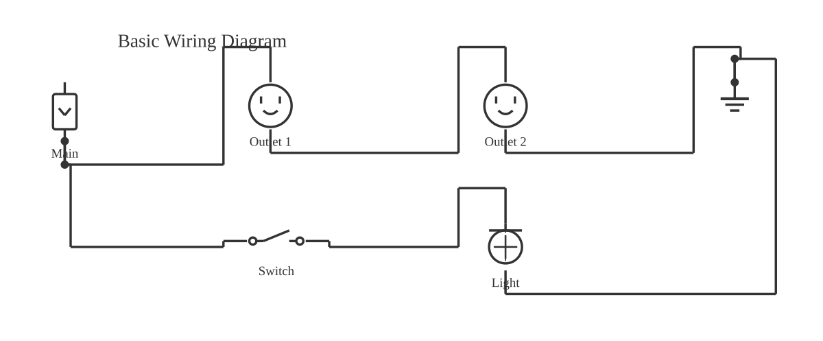
This is a free printable circuit diagram vs wiring diagram: download the diagram as SVG or open it and print to paper or PDF.
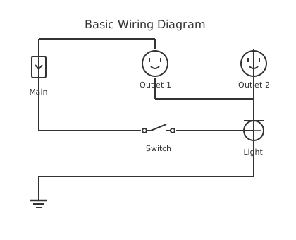
A circuit diagram shows the functional and electrical relationships within a circuit using standardised symbols and logical layout, while a wiring diagram shows the physical wire routing, terminal connections, wire colours, and real component locations needed to build or maintain that circuit. The two documents serve fundamentally different purposes: circuit diagrams are used for design, analysis, and simulation; wiring diagrams are used for installation, commissioning, and maintenance. Using one where the other is needed is one of the most common — and most consequential — mistakes in electrical documentation.
Diagram checks and scope
- Components
- 6
- Wired connections
- 6
- Automated check
- Automated pin, route, source, and topology checks passed; this is not a safety certification.
A circuit diagram is a graphical representation of how a circuit functions. The governing principle is that electrical relationships — not physical positions — determine how the diagram is drawn. Component symbols are placed where they best communicate the circuit's logic: inputs on the left, outputs on the right, power rails at top and bottom, and logical subcircuits grouped together. The underlying standard for circuit diagram symbols in international practice is IEC 60617, which defines hundreds of graphical symbols for passive components, active devices, power equipment, and control elements. North American practice follows ANSI/IEEE 315. The broader documentation framework is covered by DIN EN 61082 (identical to IEC 61082), which specifies rules for the preparation of all electrical documents including circuit diagrams.
Circuit diagrams are themselves a family of subtypes. A schematic diagram (also called an elementary diagram) is the most common type, showing individual components with their values and reference designators. A block diagram abstracts the circuit into functional subsystems — boxes labelled 'power supply,' 'amplifier,' 'microcontroller' — without showing individual components. A logic diagram uses logic gate symbols (AND, OR, NOT, NAND) to represent digital circuits. A timing diagram shows signal states over time and is used to document the behaviour of digital interfaces and state machines. Each subtype serves a different stage of the design and documentation process.
A wiring diagram takes an entirely different approach. It answers the question an installer or maintenance technician actually asks: which physical terminal does this wire connect to? Components are drawn in positions that reflect their real location on a panel, chassis, or structure. Lines represent actual wires and carry annotations that have no equivalent on a circuit diagram: wire colour, conductor cross-section, wire number, ferrule identifier, and terminal block row and position. A residential wiring diagram will identify cable types (NM-B 14/2 in North America), circuit breaker amperage, outlet positions, and switch wiring per NEC Article 210 conventions. An automotive wiring diagram will specify wire colours using the OEM colour code system, connector part numbers, and splice locations per SAE J1127 or the OEM workshop manual. An industrial connection diagram for a motor control centre will show terminal strip X1 through XN with every incoming and outgoing wire identified by its wire number and destination.
Understanding the types of wiring diagrams matters as much as understanding the types of circuit diagrams. A point-to-point wiring diagram shows every wire as an individual line running from source terminal to destination terminal — the most complete form, essential for complex panels but potentially messy for simple circuits. A ladder (daisy-chain) wiring diagram organises wiring in a way that mirrors the ladder logic schematic, making it easier to follow control circuit wiring in motor control centres. A panel layout drawing is a specific wiring diagram subtype that shows the physical arrangement of DIN-rail mounted components, cable duct routing, and terminal block positions inside an enclosure — essential for panel builders.
Industry standards govern both types. For circuit diagrams in industrial machinery, IEC 60617 and NFPA 79 apply; in power distribution, IEEE 315 and DIN EN 81346 define the reference designation system that links every circuit diagram symbol to a physical device. DIN EN 81346 is particularly important in international projects: it defines a hierarchical reference designation scheme (function designator, location designator, product designator) that allows any device on any diagram to be uniquely identified across a multi-volume documentation set. For wiring diagrams, NFPA 79 mandates their inclusion in the documentation package for industrial machinery sold in North America; IEC 61082 provides the equivalent international framework; VDE 0100 applies to low-voltage electrical installations in Germany and influences practice across Europe.
Compliance and legal requirements add another dimension that most resources on this topic ignore. CE marking documentation for machinery sold in the European Union under the Machinery Directive requires both circuit diagrams and wiring diagrams in the technical file. UL listing for industrial control panels requires wiring diagrams that demonstrate compliance with UL 508A (industrial control panels) or UL 845 (motor control centres). Without correctly prepared wiring diagrams in the format required by the applicable standard, a control panel cannot be listed or marked. Circuit diagrams alone are insufficient for these compliance purposes.
SPICE simulation is one of the most important circuit diagram use cases and one that competitors entirely overlook. Tools such as LTspice, Ngspice, and online simulators extract a netlist from the circuit diagram — a structured text file describing every component and its connections — and solve the circuit equations to predict voltage, current, and frequency behaviour. This simulation capability is only possible because circuit diagrams encode the circuit's topology in a mathematically unambiguous way. Wiring diagrams cannot be used for simulation: they describe physical connections, not functional relationships, and lack the component value annotations required by circuit solvers.
How to read a wiring diagram for a home light switch: locate the circuit breaker supplying the circuit; trace the line (black) conductor from the panel to the switch box terminal; confirm that the switched line continues from the switch output terminal to the light fixture terminal; verify that the neutral (white) conductor runs directly from the panel to the fixture without interruption; check that the ground (green or bare) conductor connects to the switch green screw and the fixture ground terminal. This physical tracing exercise is impossible on a circuit diagram, which shows the same circuit as a source, a switch symbol, and a lamp symbol with no spatial information.
How to read a circuit diagram for an LED driver: identify the supply voltage node (VCC); trace the current path from VCC through the current-limiting resistor (check its value: R = (VCC − Vf) / If); through the LED symbol (note forward voltage Vf typical for the colour); to ground (GND). Verify that the resistor power rating (P = If² × R) is within the component's specification. This analysis is immediate on a circuit diagram and practically impossible on a wiring diagram, which would show a wire from a terminal block row to a resistor body to an LED body without indicating values.
The best software tools differ by diagram type. For circuit diagrams: KiCad and Altium Designer for PCB schematics; LTspice for simulation schematics; circuitdiagrammaker.com for general-purpose circuit and schematic diagrams online. For wiring diagrams: AutoCAD Electrical and EPLAN Electric P8 for professional industrial panel documentation; Fritzing for simple pictorial wiring diagrams; circuitdiagrammaker.com for browser-based wiring diagram creation with no download. Visio is commonly used for functional block diagrams but lacks the electrical symbol depth needed for detailed schematics.
Stop switching between tools. Our free wiring diagram and circuit diagram editor handles both formats with one click — pick a template, drag in your components, and export as PDF or SVG.
How to wire circuit diagram vs wiring diagram
- Define the project scope and select diagram types needed Determine whether you need a circuit diagram for design and analysis, a wiring diagram for installation, or both. Most projects requiring CE marking, UL listing, or professional panel documentation require both.
- Create the circuit diagram first Draw the circuit diagram (schematic) using the appropriate symbol standard (IEC 60617 or ANSI/IEEE 315). Assign reference designators to every component and add component values or part numbers. Verify the design using KVL/KCL analysis or SPICE simulation.
- Assign wire numbers and terminal identifiers Once the circuit diagram is finalised, number every electrical node following your chosen scheme: IEC node-based numbering (same number at every point on a node) or JIC wire-segment numbering (unique number per wire segment). Add terminal block row and position identifiers.
- Create the wiring diagram from the circuit diagram Redraw with components in physical panel positions. Annotate every wire with number, colour, gauge, and source/destination terminals. Add a terminal-block schedule listing every wire's from-to information.
- Validate compliance requirements Check the wiring diagram against NFPA 79 (industrial machinery), UL 508A (control panels), or the applicable NEC article (residential/commercial). Confirm that all required information — wire numbers, terminal identifiers, component reference designators — appears on both documents.
- Perform a cross-document check Verify that every reference designator and node/wire number on the wiring diagram corresponds to an equivalent entry on the circuit diagram. Any discrepancy must be resolved before the documentation package is issued for fabrication or installation.
- Issue and control document revisions Assign a revision number and date to both documents. Establish a change control procedure: any field modification must be captured as a red-line on both the circuit diagram and the wiring diagram, then formally incorporated into the next issued revision.
Specifications
| Primary purpose | Circuit diagram: show functional and electrical relationships | Wiring diagram: show physical wire routing and terminal connections |
|---|---|
| Abstraction level | Circuit diagram: high — abstract symbols, logical layout | Wiring diagram: low — components shown in physical positions with real wire annotations |
| Shows physical location | Circuit diagram: no — components placed for logical clarity | Wiring diagram: yes — component positions reflect actual panel or chassis layout |
| Shows current flow | Circuit diagram: yes — explicitly through symbol arrangement and traceable paths | Wiring diagram: implicitly, through wire routing |
| Wire colours and gauges shown | Circuit diagram: no | Wiring diagram: yes — wire colour, cross-section, and wire number annotated on every conductor |
| Connector pinouts shown | Circuit diagram: no | Wiring diagram: yes — terminal numbers and connector pin identifiers are core content |
| Best for | Circuit diagram: design, analysis, SPICE simulation, CE/UL documentation | Wiring diagram: installation, commissioning, field maintenance, panel fabrication |
| Governing standards | Circuit diagram: IEC 60617, ANSI/IEEE 315, DIN EN 61082 | Wiring diagram: NFPA 79, IEC 61082, VDE 0100, NEC, SAE J1127 |
| Reference designation system | Circuit diagram: DIN EN 81346 (IEC 81346) hierarchical designators | Wiring diagram: same designators plus wire numbers and terminal numbers |
| Used for SPICE simulation | Circuit diagram: yes — netlist extracted directly | Wiring diagram: no |
| Required for CE marking / UL listing | Circuit diagram: yes (as technical file / panel documentation) | Wiring diagram: yes — both required together |
| Typical software | Circuit diagram: KiCad, Altium, LTspice, circuitdiagrammaker.com | Wiring diagram: AutoCAD Electrical, EPLAN Electric P8, circuitdiagrammaker.com |
Safety warnings
- A wiring diagram that does not match the as-built panel is the single most dangerous document in industrial electrical maintenance. Never assume a wiring diagram is current without physically verifying at least three random connections against the drawing before working in the panel.
- Circuit diagrams do not show conductor ampacity or short-circuit protection ratings. Always consult the wiring diagram and cable schedule for wire size, and verify that over-current protection devices are correctly rated before energising.
- Automotive wiring diagrams use OEM-specific colour codes and connector pin numbering that differ between manufacturers and even between model years. Using a wiring diagram from the wrong build year can result in miswiring airbag, fuel injection, or ABS systems — all safety-critical.
- For SPICE simulation derived from a circuit diagram: simulation predicts ideal behaviour. Real circuits are subject to parasitic inductance, capacitance, and resistance not shown on the circuit diagram. Do not use simulation results alone to confirm safe operating temperatures or insulation ratings.
Tools needed
- circuitdiagrammaker.com — free browser-based editor for both circuit diagrams and wiring diagrams, IEC and ANSI symbols, PNG/SVG/PDF export
- KiCad (free, open-source) — schematic capture and PCB layout with netlist export and BOM generation for electronics circuit diagrams
- AutoCAD Electrical or EPLAN Electric P8 — professional tools that maintain a live link between circuit diagram and wiring diagram, automate wire numbering, and generate terminal-block schedules
- LTspice (free, from Analog Devices) — SPICE simulation tool that takes circuit diagrams as input for voltage, current, and frequency analysis
- Multimeter and wire tracer — for verifying wiring diagrams against physical as-built panels during commissioning or maintenance
- DIN EN 81346 reference — for assigning hierarchical reference designators that are consistent across circuit diagrams and wiring diagrams on large international projects
Common mistakes
- Trying to install or wire a panel from a circuit diagram alone — circuit diagrams lack wire colours, gauges, terminal numbers, and physical layout information essential for accurate installation.
- Omitting wire numbers from the wiring diagram, forcing installers to trace wires physically rather than follow documentation, which multiplies commissioning time and error risk.
- Inconsistently applying reference designators — using 'Relay 1' on the circuit diagram and 'K1' on the wiring diagram for the same device causes cross-referencing failures.
- Using wiring diagrams to verify circuit logic during troubleshooting without first consulting the circuit diagram, leading to time-wasted physical tracing of connections that the schematic would have resolved in seconds.
- Creating the wiring diagram before the circuit diagram is finalised, then failing to update it when the design changes — the most common cause of as-built documentation errors in panel shops.
- Confusing DIN EN 61082 and DIN EN 81346: the former governs how documents are prepared, the latter governs how devices are designated. Both are needed for compliant documentation on international projects.
Troubleshooting
- Panel wiring does not match the wiring diagram
- Cause: Field modifications were made during commissioning and not documented, or the panel was fabricated from an earlier (superseded) revision of the wiring diagram. Fix: Red-line the wiring diagram by physically tracing every wire and noting discrepancies. Cross-check against the circuit diagram to determine the design intent. Issue a revised wiring diagram incorporating the verified as-built state, with a revision note explaining the change.
- Circuit behaves correctly on the circuit diagram simulation but fails in the physical panel
- Cause: The wiring diagram has an error — two wires swapped, a terminal misnumbered, or a wire omitted — that was not present in the circuit diagram. Fix: Isolate the faulty subcircuit using the circuit diagram to understand expected behaviour, then use the wiring diagram to locate the specific terminal discrepancy. Correct the wiring, then update the wiring diagram to reflect the fix.
- Wire number on the terminal block cannot be found on the wiring diagram
- Cause: The wire was added during a field modification and not incorporated into the documentation, or the wire was pre-existing from an earlier project version. Fix: Trace the wire to its source and destination terminals. Identify which node on the circuit diagram it corresponds to. Add the wire to the wiring diagram with a clear revision note, and verify that no other wire currently carries the same number.
- SPICE simulation of the circuit diagram shows oscillation that does not appear in hardware
- Cause: The SPICE model includes ideal component behaviour; real components have tolerances, parasitic elements, and thermal effects that stabilise the circuit in practice. Fix: Add parasitic elements (series resistance for capacitors, ESL for inductors, trace inductance) to the circuit diagram simulation. Use measured component values rather than nominal values. If stability is marginal in simulation, it may still be marginal in hardware under worst-case conditions — investigate further before production.
- Residential wiring diagram does not account for AFCI or GFCI protection requirements
- Cause: The diagram was drawn to an older code cycle or is based on a template that predates recent NEC updates requiring AFCI protection on bedroom circuits and GFCI protection in wet locations. Fix: Cross-reference the wiring diagram against the current edition of NFPA 70 (NEC) for the applicable jurisdiction. Add AFCI breakers at the panel for required circuits and add GFCI devices at the first outlet in each required wet-location chain. Update the wiring diagram to show the protection devices explicitly.
Frequently asked questions
What is the main difference between a circuit diagram and a wiring diagram?
A circuit diagram shows how a circuit functions — its logic, component values, and electrical relationships — using standardised abstract symbols. A wiring diagram shows how to physically build or maintain the circuit, specifying wire colours, gauges, terminal numbers, and component locations. Both are needed for most real-world electrical projects.
Can a circuit diagram be used instead of a wiring diagram for installation?
No. A circuit diagram does not show wire colours, conductor gauges, terminal numbers, or physical device locations — all the information an electrician needs to wire a panel or connect a circuit correctly. Attempting installation from a circuit diagram alone leads to wiring errors, failed inspections, and safety hazards.
Which diagram do electricians use on a job site?
Residential and commercial electricians primarily use wiring diagrams and panel schedules. Industrial controls electricians use both: circuit diagrams (often in ladder form) to understand relay and PLC logic, and wiring/connection diagrams to wire panels correctly. Having both documents on site is standard practice for industrial commissioning.
What is a ladder diagram and is it a circuit or wiring diagram?
A ladder diagram is a type of circuit diagram — specifically a schematic — used in industrial motor control and PLC programming. It represents the control circuit as horizontal rungs between two vertical power rails. It is not a wiring diagram; it shows circuit logic, not physical wire connections. The corresponding wiring diagram for the same panel is a separate document.
Which diagram is required for CE marking or UL listing?
Both are required. CE marking documentation under the Machinery Directive includes circuit diagrams and wiring diagrams in the technical file. UL 508A (industrial control panels) requires wiring diagrams demonstrating panel construction compliance. Neither document alone is sufficient for certification.
What is the difference between a point-to-point wiring diagram and a ladder (daisy-chain) diagram?
A point-to-point wiring diagram shows each wire as a line running directly from its source terminal to its destination terminal. A daisy-chain (ladder) wiring diagram groups wires by voltage level or circuit function and routes them sequentially through terminal blocks, mirroring the structure of the ladder logic schematic. Point-to-point is more explicit; daisy-chain is more compact for larger panels.
How do I convert a circuit diagram into a wiring diagram?
The conversion involves: assigning reference designators to all devices; determining physical component positions on the panel; assigning wire numbers to every electrical node; redrawing with components in physical positions, annotating every wire with number, colour, and gauge; and generating a terminal-block schedule. Software such as AutoCAD Electrical and EPLAN Electric P8 automates this process by maintaining a live link between the two document types.
What free software can draw both circuit diagrams and wiring diagrams?
circuitdiagrammaker.com is a free browser-based editor that supports both. It provides IEC and ANSI schematic symbol libraries for circuit diagrams and wiring diagram templates, with PNG, SVG, and PDF export. No account or download is required. For PCB-specific circuit diagrams, KiCad is free and open-source.
Sources and verification
Review status: Not independently reviewed. Automated topology checks confirm stored terminals and routes, not the correctness of manufacturer pin assignments, ratings, regional codes, or installation decisions. Verify those claims against the current primary documentation before use.
- IEC 61082-1:2014 — Rules for electrotechnical documents — International Electrotechnical Commission. Supports: General diagram, drawing, table, and reference-designation presentation conventions. Checked 2026-07-15.
Related diagrams
- 4 to 2 encoder circuit diagram
- 7265 ic circuit diagram
- arduino circuit diagram
- arduino uno circuit diagram
- breadboard circuit diagram
- encoder circuit diagram