Wiring Diagram vs Schematic: What's the Difference and When to Use Each
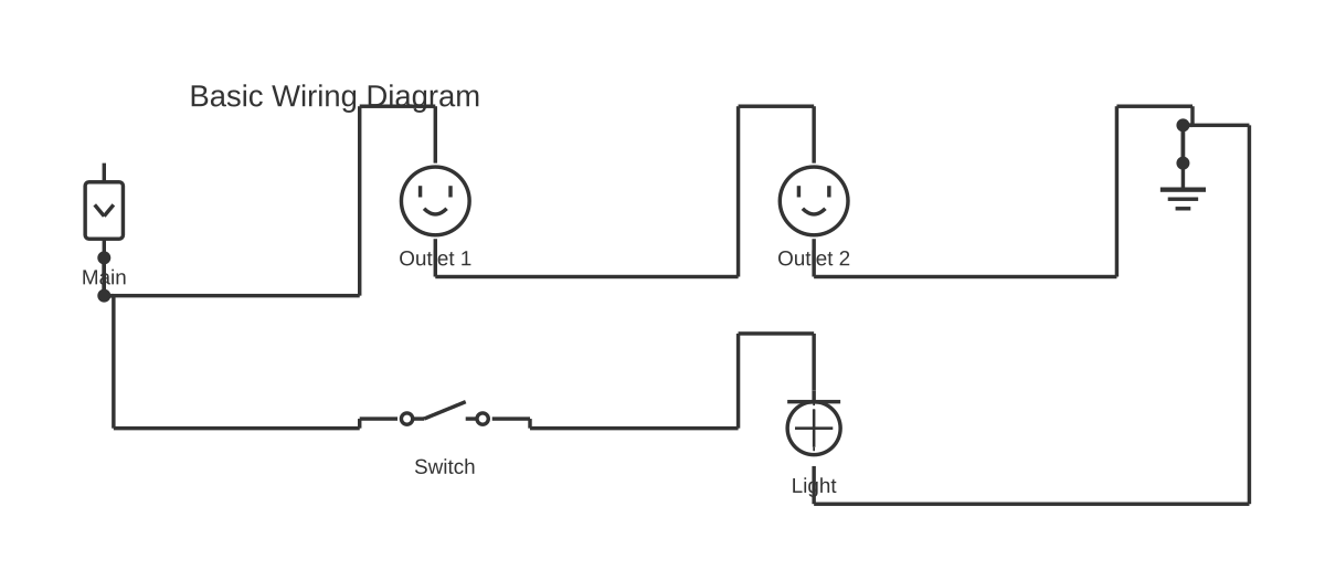
This is a free printable wiring diagram vs schematic: download the diagram as SVG or open it and print to paper or PDF.
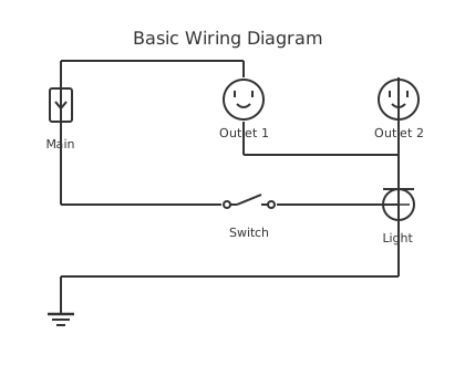
A schematic diagram shows the logical function of a circuit using standardised abstract symbols, while a wiring diagram shows the physical wire connections, routing, terminal numbers, and real component locations. They are not interchangeable: schematics are the tool of engineers and technicians analysing circuit behaviour; wiring diagrams are the tool of electricians and installers doing physical work. Understanding which document to reach for — and why — prevents costly mistakes on every project from home wiring to industrial motor control.
A schematic diagram, sometimes called a circuit schematic or elementary diagram, is a purely logical representation of an electrical circuit. Every component is drawn using a standardised symbol — a zigzag line for a resistor in ANSI/IEEE 315, a rectangle in IEC 60617; a circle with an X for a lamp; a parallel-line pair for a capacitor — and the symbols are arranged to make the circuit's behaviour easy to analyse, not to reflect where the parts physically sit. The interconnecting lines show electrical connections, not wire paths. A relay coil and its associated normally open (NO) contact may be drawn centimetres apart on the page even though both are housed in the same relay module on the panel.
This abstraction is deliberate and powerful. Because components are laid out in functional order, a trained reader can immediately trace current paths, identify series and parallel branches, spot where a control transformer steps the voltage down before feeding a relay logic rung, and verify that protective devices are positioned correctly. Ladder diagrams — the schematic form universally used in industrial motor control — carry this logic further: each rung is read left-to-right like a line of text, with the power rails on the outside and the logic (contacts, coils, timers) in between. Siemens, Eaton, and every other control gear manufacturer publish ladder-form schematics for their starters, variable-speed drives, and protection relays.
Standards that govern schematic diagrams include IEC 60617 (the international symbol library used across Europe, Asia, and Australia), ANSI/IEEE 315 (the North American equivalent), and NFPA 79 for industrial machinery. These standards define not only symbol shapes but also reference designator conventions: the letter-number codes (K1 for a relay, F1 for a fuse, M1 for a motor) that let you cross-reference every symbol on a schematic back to a specific physical device.
A wiring diagram takes a completely different approach. Its job is to answer the installer's question: which wire goes where? Rather than abstract symbols, wiring diagrams show components in a layout that approximates their physical positions, connected by lines that represent actual wires. Those lines carry annotations that matter on the job site: wire colour, conductor gauge, wire number, and terminal block number. A wiring diagram for a residential light-switch circuit will show the cable entering the switch box, identify the black (line), white (neutral), and green/bare (ground) conductors, and indicate the terminal screw each connects to. An industrial connection diagram for a motor control centre panel will show every terminal strip row, the ferrule numbers crimped onto each wire end, and the wire routing between devices.
Residential wiring diagrams follow NEC (National Electrical Code) conventions and are primarily used by licensed electricians and homeowners for planning circuits, understanding breaker panel layouts, and locating existing circuits for renovation work. Automotive wiring diagrams have their own conventions — wire colour codes tied to SAE and OEM standards, connector pinout tables, and splice locations — that are essential for auto technicians but would be unfamiliar to an industrial electrician. Industrial connection diagrams, produced to NFPA 79 or IEC 61082, form the core of the as-built documentation package for control panels and machinery.
Understanding the wire numbering schemes used in wiring diagrams prevents confusion between projects. The IEC numbering scheme assigns numbers at each node (connection point), so every wire at a junction carries the same number. The JIC (Joint Industrial Council) scheme, common in North American shops, assigns a number to each wire segment, meaning a wire can change number as it passes through a terminal block. Neither system is inherently superior; knowing which your documentation uses is critical for accurate maintenance.
The troubleshooting workflow on real-world projects combines both documents. An experienced technician always begins with the schematic to understand what the circuit is supposed to do: trace the logic, identify the control transformer secondary, follow the relay rung, determine which contacts must be closed for the output coil to energise. Once the fault is logically isolated to a particular device or node, the wiring diagram answers the practical question: which physical terminal do I put my meter probe on? This two-step approach — schematic first, wiring diagram second — is taught in every industrial electrical apprenticeship programme and is the method implicitly used by appliance repair technicians who consult schematic pocket cards before probing connectors.
The conversion process from schematic to wiring diagram is a genuine engineering task that no competitor explains but that every panel builder performs. The steps are: (1) assign reference designators to every device shown on the schematic; (2) determine physical device locations on the panel or chassis; (3) assign wire numbers to every node; (4) redraw with components in their physical positions, annotating every connection with wire number, colour, and gauge; (5) generate a terminal-block schedule listing source device, source terminal, destination device, and destination terminal for every wire. Software such as AutoCAD Electrical and EPLAN Electric P8 automates this workflow, maintaining a live link between the schematic and the wiring diagram so that an engineering change on one propagates to the other.
For learning purposes, schematics have a steeper initial learning curve — you must memorise or reference the symbol vocabulary — but once mastered they are far faster to read than wiring diagrams because every circuit fits on fewer pages. Wiring diagrams are more accessible to beginners because the visual connection to the real world is obvious, but large wiring diagrams for complex panels can run to hundreds of pages.
Emerging digital-twin and SaaS-based documentation tools can auto-generate wiring diagrams from a schematic netlist, compressing what once took days of draughting into minutes. This represents the future of panel documentation and is a workflow shift that purely paper-based or static-CAD shops are beginning to adopt.
Ready to draw your own schematic or wiring diagram? Open our free online editor — no download required — and choose from professional IEC or ANSI schematic symbol libraries or start from a wiring diagram template.
How to wire wiring diagram vs schematic
- Identify your goal first Determine whether you need to analyse or design the circuit (schematic) or install and wire it (wiring diagram). The goal dictates which document to create or consult.
- Gather symbol standards If drawing a schematic, choose IEC 60617 (international) or ANSI/IEEE 315 (North American) and use it consistently throughout. Mixing standards on one drawing causes errors and fails audits.
- Draft the schematic (logical layer first) Place components in functional order — inputs on the left, outputs on the right — and connect them with lines representing electrical nodes. Assign reference designators (K1, F1, M1) to every device.
- Assign wire numbers and colours Once the schematic is complete and verified, annotate every node with a wire number following your chosen numbering scheme (IEC node-based or JIC segment-based). Add wire colour and gauge per your standard (NEC, SAE, or IEC colour code).
- Create the wiring diagram from the schematic Redraw with components in their physical panel positions. Connect devices using annotated wire lines showing wire number, colour, gauge, and terminal identifier. Generate a terminal-block schedule from the result.
- Cross-reference both documents Verify that every wire number appearing on the wiring diagram corresponds to a node on the schematic. Any discrepancy indicates a drawing error that must be resolved before fabrication or installation begins.
- Review against the applicable standard Check the schematic against NFPA 79 or IEC 61082 requirements for the project type (industrial machinery, residential, automotive). Confirm that over-current protection devices appear on both documents and are consistently referenced.
Specifications
| Primary purpose | Schematic: shows circuit logic and function | Wiring diagram: shows physical wire connections and routing |
|---|---|
| Level of abstraction | Schematic: high — uses standardised abstract symbols | Wiring diagram: low — shows real component appearance and physical layout |
| Component placement | Schematic: logical/functional order only | Wiring diagram: reflects actual physical location on panel or chassis |
| Wire representation | Schematic: single lines showing electrical connections | Wiring diagram: actual wire colours, gauges, numbers, and routes |
| Best for | Schematic: design, analysis, troubleshooting logic | Wiring diagram: installation, commissioning, field maintenance |
| Primary audience | Schematic: engineers, controls technicians | Wiring diagram: electricians, panel installers, field workers |
| Governing standards | Schematic: IEC 60617, ANSI/IEEE 315, NFPA 79 | Wiring diagram: NFPA 79, IEC 61082, NEC |
| Typical use case | Schematic: control panel design, motor control, PCB layout | Wiring diagram: home wiring, automotive, HVAC, panel as-builts |
| Shows current path | Schematic: yes, explicitly through symbol arrangement | Wiring diagram: implicitly through wire routing |
| Wire numbering scheme | Schematic: node labels / net labels | Wiring diagram: IEC node numbering or JIC wire-segment numbering |
| Learning curve | Schematic: steeper — requires symbol vocabulary | Wiring diagram: more intuitive for beginners |
| Interchangeable? | No — serve fundamentally different audiences and purposes on the same project |
Safety warnings
- Never use a wiring diagram alone to verify that a circuit is de-energised before working on it. Always use a calibrated voltage tester on the physical terminals identified by the wiring diagram after tracing the isolation path on the schematic.
- Incorrect wire colour interpretation across standards (NEC vs IEC vs automotive) has caused electrocution incidents. Always confirm the colour code convention for the specific project before energising.
- Do not assume a schematic represents the as-built wiring. Field modifications are frequently made without updating drawings. Verify against the physical installation before trusting either document for live work.
- Industrial schematics for motor control often include 480 V or higher power circuits on the same sheet as 120 V control circuits. Clearly identify voltage levels on both the schematic and wiring diagram, and verify isolation before probing any terminal.
Tools needed
- Free online diagram editor (circuitdiagrammaker.com) — supports IEC and ANSI schematic symbols and wiring diagram templates, PNG/SVG/PDF export
- IEC 60617 or ANSI/IEEE 315 symbol reference card — for correctly identifying components on unfamiliar schematics
- Calibrated multimeter or clamp meter — for verifying voltage levels at terminals identified on wiring diagrams
- Wire number label printer (Brady, HellermannTyton) — for marking conductors to match the wiring diagram's wire number annotations
- Terminal-block schedule spreadsheet — for systematically listing every wire's source device, source terminal, destination device, and destination terminal
- AutoCAD Electrical or EPLAN Electric P8 — for professional panel documentation that auto-generates wiring diagrams from schematics
Common mistakes
- Using a wiring diagram to analyse circuit logic — wiring diagrams do not show current paths clearly and will mislead troubleshooting efforts when the physical layout obscures the functional sequence.
- Mixing IEC 60617 and ANSI/IEEE 315 symbols on the same schematic, creating ambiguity for readers trained in only one standard.
- Omitting reference designators from schematics, making it impossible to cross-reference schematic symbols to physical devices on the wiring diagram or panel BOM.
- Confusing wire colours between standards — NEC residential colour codes (black/white/green) differ from IEC industrial codes (brown/blue/green-yellow) and automotive OEM codes, leading to miswiring.
- Treating the wiring diagram as the primary design document and skipping the schematic step entirely, which hides logic errors that only become apparent during commissioning.
- Using JIC wire numbering on a project that will be shipped internationally, where the receiving technician's training assumes IEC node numbering.
Troubleshooting
- Schematic symbols not matching physical components
- Cause: The schematic was drawn to ANSI/IEEE 315 but the components sourced are labelled with IEC 60617 markings, or vice versa. Fix: Identify which standard was used on the schematic (check the title block) and obtain the corresponding symbol reference. Create a legend on the drawing showing any non-standard symbols used.
- Wire number on wiring diagram does not appear on schematic
- Cause: A field modification was made to the panel after the original documentation was issued, or the wiring diagram was created independently without referencing the schematic. Fix: Trace the physical wire back to its origin terminal, identify which schematic node it corresponds to, and update both documents. Mark the revision with date and engineer initials.
- Circuit behaves differently from schematic prediction
- Cause: The wiring diagram (as-built) differs from the schematic — a common result of undocumented field changes or a panel builder misreading a symbol. Fix: Red-line the schematic by physically tracing the wiring diagram terminal by terminal and noting every discrepancy. Determine the intended design intent and correct either the wiring or the schematic accordingly.
- Relay contact shown as NO on schematic but panel wired as NC
- Cause: Confusion between normally open (NO) and normally closed (NC) contact symbols, which differ subtly between IEC 60617 and ANSI/IEEE 315. Fix: Cross-check the relay datasheet pinout against the wiring diagram terminal number. Rewire using the correct contact terminal (usually labelled 13/14 for NO, 11/12 for NC on standard IEC relays).
- Automotive wiring diagram shows a wire colour not present in the vehicle
- Cause: The diagram is from a different model year or trim level, or it uses a generic wire colour convention rather than the OEM-specific pinout for that build date. Fix: Obtain the OEM workshop manual for the exact VIN build range. Verify connector pinouts with a breakout box rather than backprobing, to avoid damaging waterproof connector seals.
Frequently asked questions
Is a wiring diagram the same as a schematic?
No. A schematic shows the logical function of a circuit using standardised abstract symbols arranged for analysis. A wiring diagram shows the physical wire connections, routing, terminal numbers, and real component positions for installation and maintenance. Both documents are often required for the same project.
Which diagram should I use for troubleshooting an electrical fault?
Start with the schematic to understand the circuit logic and isolate which device or node should be at fault. Then switch to the wiring diagram to find the physical terminal or connector to probe. Using the schematic alone can leave you unsure where to place your meter; using the wiring diagram alone means you may miss a logical branch entirely.
What is a ladder diagram and how does it relate to schematics?
A ladder diagram is a specific form of schematic used in industrial motor control and PLC programming. It represents the circuit as horizontal rungs between two vertical power rails, making the control logic easy to read sequentially. Every ladder diagram is a schematic, but not every schematic is a ladder diagram.
Do electricians use schematics or wiring diagrams on the job?
Residential and commercial electricians primarily use wiring diagrams and panel schedules, which show physical cable routes and terminal connections. Industrial controls electricians use both: the schematic to understand relay and PLC logic, and the wiring diagram (connection diagram) to wire the panel correctly. Appliance repair technicians rely heavily on schematics printed inside appliance covers.
Can a single diagram be both a schematic and a wiring diagram?
Rarely, and only for very simple circuits. For anything beyond a basic two-component circuit the functional clarity of a schematic and the physical accuracy of a wiring diagram are in direct conflict — you cannot optimise both on the same drawing. In practice, professional documentation always separates them.
What is the difference between a connection diagram and a wiring diagram?
In strict IEC and NFPA 79 terminology, a connection diagram (also called a terminal diagram) focuses specifically on the interconnections between terminal blocks and external devices, whereas a wiring diagram shows all internal and external wiring. In everyday use, the terms are often used interchangeably, especially in North America.
What software can I use to draw a wiring diagram or schematic for free?
circuitdiagrammaker.com provides a free browser-based editor with both IEC and ANSI symbol libraries for schematics and wiring diagram templates. No download or account is required. Commercial options include AutoCAD Electrical and EPLAN for professional panel documentation.
What do IEC 60617 and ANSI/IEEE 315 cover?
IEC 60617 is the international standard (published by the International Electrotechnical Commission) defining graphical symbols for electrical diagrams, used widely outside North America. ANSI/IEEE 315 is the North American equivalent. They specify symbol shapes for every common electrical component — resistors, capacitors, switches, relay coils, contacts, transformers, motors, and more.