Control Diagram of Star Delta Starter: Timer, Interlocking and Transition Logic
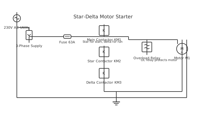
This is a free printable control diagram of star delta starter: download the diagram as SVG or open it and print to paper or PDF.
The star-delta starter control diagram shows how a timer relay coordinates three contactors to first connect the motor in star configuration for reduced-voltage starting, then transition automatically to delta after the programmed acceleration time.
Diagram checks and scope
- Components
- 9
- Wired connections
- 11
- Automated check
- Automated pin, route, source, and topology checks passed; this is not a safety certification.
Star-delta starting reduces motor starting current to approximately one third of direct-on-line (DOL) starting current by initially connecting motor windings in star, which applies line-to-neutral voltage (231 V on a 400 V system) across each winding rather than the full line-to-line voltage. After the motor accelerates to approximately 70–80 percent of full speed in star, the control circuit transitions the winding configuration to delta, restoring full line-to-line voltage across each winding for full-torque operation. The power circuit requires three contactors: the main contactor KM1 connects L1, L2, L3 to motor terminals U1, V1, W1 and remains closed throughout operation. The star contactor KM3 links motor terminals U2, V2, W2 together at a neutral point during starting. The delta contactor KM2 connects U2 to V1, V2 to W1, and W2 to U1 during running, forming the delta winding configuration. The control circuit operates as follows: pressing start energises the main contactor coil KM1 and the star contactor coil KM3 simultaneously, placing the motor in star. The timer relay TDR (time delay relay) starts timing simultaneously. When the TDR times out after the programmed star duration (typically 5–15 seconds), its time-delayed contact opens the star contactor coil KM3 and closes the delta contactor coil KM2. Crucially, an interlocking arrangement ensures KM2 and KM3 can never energise simultaneously, because simultaneous energisation would short-circuit the motor windings. The interlock is achieved by wiring a normally-closed auxiliary contact of KM3 in series with the KM2 coil, and a normally-closed auxiliary contact of KM2 in series with the KM3 coil. A short transition break of approximately 30 ms between star opening and delta closing allows flux in the motor windings to decay before delta connection, reducing the transition current transient. Some modern electronic star-delta timers incorporate this break-before-make timing internally.
How to wire control diagram of star delta starter
- Wire main contactor KM1 Connect L1, L2, L3 to KM1 input terminals 1, 3, 5. Connect KM1 output terminals 2, 4, 6 to motor terminals U1, V1, W1 via the overload relay. KM1 remains closed throughout star and delta operation.
- Wire star contactor KM3 Connect motor terminals U2, V2, W2 to KM3 main contacts so that when KM3 closes, all three motor winding ends are shorted together forming the star neutral point. KM3 line side terminals connect to a common bus.
- Wire delta contactor KM2 Wire KM2 to connect U2 to the junction of W1 and KM1-output L3, V2 to U1 and L1 junction, W2 to V1 and L2 junction — forming the delta cross-connections between winding ends and starts of adjacent phases.
- Wire control circuit Connect start button to KM1 coil. KM1 NO auxiliary powers KM3 coil and starts TDR. TDR time-delayed NC contact de-energises KM3. TDR time-delayed NO contact energises KM2. Wire KM2 NC aux in series with KM3 coil and KM3 NC aux in series with KM2 coil for interlocking.
- Commission and verify timing Power up with no load connected to motor shaft. Observe current on all three phases with a clamp meter during start. Verify current drops at star transition and confirm delta current equals rated FLA. Adjust TDR if star current has not reduced before transition.
Specifications
| Star starting voltage per winding | Vline ÷ √3 = 231 V (on 400 V supply) |
|---|---|
| Starting current (star) | ≈33% of DOL locked-rotor current |
| Star period (typical) | 5–15 seconds (load dependent) |
| Transition break-before-make | 30–100 ms (timer or electronic relay) |
Safety warnings
- Star contactor KM3 and delta contactor KM2 must never energise simultaneously — verify mechanical and electrical interlocking before first power-on to prevent winding short circuit.
- The transition current spike during star-to-delta changeover can exceed DOL starting current briefly — never reduce the transition timer below 5 seconds to allow adequate motor acceleration.
- Verify all six motor terminals U1, V1, W1, U2, V2, W2 are accessible and correctly identified before wiring — terminal reversal in star or delta configuration causes winding damage.
Tools needed
- Phase sequence meter to verify L1-L2-L3 order before first start
- Clamp-on ammeter for measuring starting and running current on all three phases
- Timer relay tester or stopwatch for verifying TDR transition timing
- Digital multimeter for coil voltage verification and auxiliary contact testing
Common mistakes
- Wiring KM2 delta connections incorrectly — each motor winding end must connect to the start of the next phase, not to the same phase end.
- Setting the star duration timer too short, transitioning to delta before the motor reaches sufficient speed and causing a large transition current spike.
- Omitting the electrical interlock between KM2 and KM3 relay coils, relying only on mechanical interlocking, which can fail due to worn armature guides.
Troubleshooting
- Motor starts but does not transition to delta
- Cause: TDR timer not functioning or TDR time-delayed contact not wired correctly Fix: Measure voltage at TDR coil terminals during start to confirm it is energised. Time the transition with a stopwatch. If TDR contacts do not operate, replace timer relay. Verify wiring matches TDR terminal diagram.
- Overload trips at delta transition
- Cause: Motor not fully accelerated before transition, causing large current spike on delta connection Fix: Increase star acceleration timer by 3–5 seconds. Verify motor current decreases in star before transition time. Check that load does not require more torque than available in star during acceleration.
- KM2 and KM3 both try to energise
- Cause: Electrical interlock not wired or NC auxiliary contacts failed open Fix: Immediately cut power. Inspect interlock wiring — NC auxiliary of KM3 must be in series with KM2 coil and vice versa. Replace any failed auxiliary contact blocks before re-energising.
Frequently asked questions
Why does star-delta starting reduce starting current?
In star connection, each motor winding sees line-to-neutral voltage (Vline divided by root 3, approximately 231 V on a 400 V supply). Motor starting current is proportional to applied voltage squared, so the current at 231 V is one third of current at 400 V. The trade-off is that starting torque is also reduced to one third of DOL torque, making star-delta unsuitable for loads requiring high starting torque.
How long should the star acceleration period be?
The star period should be long enough for the motor to reach 70–80 percent of synchronous speed before transitioning to delta. For most standard induction motors with low-inertia loads (pumps, fans), 5–10 seconds is typical. For higher-inertia loads, increase to 10–15 seconds. Monitor current during starting with a clamp meter — when running current in star drops and stabilises, the motor has accelerated sufficiently for delta transition.
What happens if the motor is still in star when the load is applied?
In star configuration, the motor produces only one third of its rated torque. If full load is applied while still in star, the motor may stall — particularly for loads requiring high torque at speed such as conveyors or compressors. The overload relay would eventually trip if the motor stalls in star. Always ensure the star period is sufficient for the motor to reach speed with the actual load before transitioning.
Can star-delta starters be used with all motors?
Star-delta starters require a motor with all six winding terminals accessible (U1, V1, W1, U2, V2, W2). Some smaller motors have only three terminals with the star or delta connection made internally — these cannot be used with star-delta starters. The motor must be rated for the lower star voltage: a motor rated 400 V delta must be suitable for 231 V in star, which is standard for 400/690 V dual-voltage motors.
What is the transition current spike and can it be reduced?
When transitioning from star to delta, the motor has residual flux and residual voltage that may be out of phase with the supply voltage at the instant of delta connection. If the phase difference is significant, the delta closure drives a large circulating current — potentially exceeding DOL locked-rotor current briefly. Electronic soft-starters or VFDs eliminate this issue entirely. Within star-delta starters, extending the timer break-before-make interval to 50–100 ms allows residual flux to decay, reducing transition spike.
Sources and verification
Review status: Not independently reviewed. Automated topology checks confirm stored terminals and routes, not the correctness of manufacturer pin assignments, ratings, regional codes, or installation decisions. Verify those claims against the current primary documentation before use.
- IEC 61082-1:2014 — Rules for electrotechnical documents — International Electrotechnical Commission. Supports: General diagram, drawing, table, and reference-designation presentation conventions. Checked 2026-07-15.
Related diagrams
- control circuit of star delta starter
- automatic star delta starter control circuit diagram
- power diagram of star delta starter
- star delta starter control circuit diagram
- star delta starter control circuit diagram with timer
- star delta starter control diagram with timer