Ladder Diagram Basics: Rungs, Contacts, Coils, and the PLC Scan Cycle

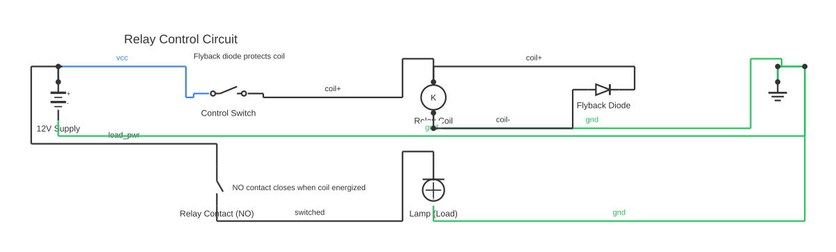
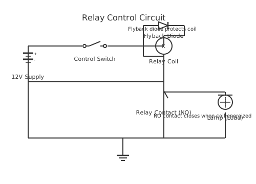
Ladder Diagram Basics — The Complete Beginner Guide — circuit diagram showing component connections+-12V SupplyControl SwitchKRelay CoilFlyback DiodeRelay Contact (NO)Lamp (Load)Relay Control CircuitFlyback diode protects coilNO contact closes when coil energized
Ladder Diagram Basics: Rungs, Contacts, Coils, and the PLC Scan Cycle — interactive diagram. Open it in the editor to customise components and wiring.

This is a free printable ladder diagram basics: download the diagram as SVG or open it and print to paper or PDF.
The basics of a ladder diagram come down to five elements: a left power rail, a right power rail, horizontal rungs connecting them, contacts on the rungs that represent conditions, and output coils at the right end that represent actions. Every PLC ladder program ever written — from a simple motor starter to a complex bottling line — is built from these five elements combined using three Boolean operations: AND (series contacts), OR (parallel branches), and NOT (normally-closed contact). This guide explains each element in precise technical detail, including the fail-safe wiring principle that separates safe industrial programs from dangerous ones.

## What Are Ladder Diagram Basics?

Ladder diagram basics refers to the fundamental building blocks of IEC 61131-3 Ladder Diagram (LD) programming — the graphical PLC language that represents control logic as a sequence of horizontal rungs between two vertical power rails. The term 'basics' covers the structural elements (rails, rungs, contacts, coils), the execution model (PLC scan cycle), and the three logical operations (AND, OR, NOT) from which all industrial control programs are composed.

The basics are foundational not just as a learning exercise but as a practical requirement: a PLC programmer who does not thoroughly understand NC contact behaviour, seal-in circuits, and the scan cycle order will write programs that work in simulation but fail — sometimes dangerously — when connected to real machinery.

## The Structure: Left Rail, Right Rail, Rungs

A ladder diagram's visual framework is two vertical lines — the **left power rail** and the **right power rail** — connected by horizontal **rungs**. The left rail represents logical continuity from the power source (logical TRUE); the right rail is the return path. Each rung is an independent boolean equation that is evaluated once per PLC scan cycle.

Logical current flows from left to right. If a continuous TRUE path exists across the rung — meaning every series condition is TRUE, or at least one parallel branch is TRUE — the output at the right rail is energised. If the path is broken anywhere, the output is de-energised. This left-to-right current metaphor comes directly from relay-logic schematics, where physical current had to flow through a closed circuit to energise a coil.

Rungs are numbered from top to bottom in the program. The PLC evaluates them in order — Rung 0 first, then Rung 1, and so on. This ordering matters: if a rung sets a bit that another rung uses as a contact, the downstream rung sees the new bit value in the same scan (because the PLC evaluates the output image table, not the input image table, for internal bits set within the program).

## XIC: The Normally-Open Contact

The **XIC (Examine If Closed)** contact is drawn as -| |- and represents a normally-open (NO) switch or sensor. It evaluates TRUE (passes logical current) when its associated bit in the PLC's data table is 1. It evaluates FALSE when the bit is 0.

When a physical NO pushbutton is connected to a PLC input terminal, pressing the button closes the circuit, driving current to the input module, which sets the corresponding input bit to 1. The XIC contact on that bit then opens the logical path — wait, let's be precise: XIC is TRUE (open to current passing) when bit = 1. So pressing the NO button → bit = 1 → XIC TRUE → current passes → output energises. This is the intuitive behaviour most engineers expect.

XIC is used for Start buttons, selector switches in the ON position, sensor outputs in the active state, and any positive condition that must be TRUE to allow an output.

## XIO: The Normally-Closed Contact

The **XIO (Examine If Open)** contact is drawn as -|/|- and represents a normally-closed (NC) switch or sensor. It evaluates TRUE when its associated bit is 0 and FALSE when the bit is 1.

When a physical NC pushbutton is connected to a PLC input, the field circuit is closed at rest, current flows to the input module, and the bit = 1. The XIO contact on that bit is FALSE when bit = 1 — but wait, that means the XIO blocks current while the NC button is at rest, which is wrong for a Stop button. The resolution: a Stop button wired NC drives the input bit to 1 when at rest, and the **rung uses XIO**. XIO is TRUE when bit = 0. When Stop is pressed, field circuit opens, bit drops to 0, XIO becomes TRUE... No — the Stop button should OPEN the rung when pressed, stopping the machine.

Let's be precise about the Stop button in a start/stop circuit: The Stop NC button physically opens the circuit when pressed. So: NOT pressed → field closed → bit = 1. Pressed → field open → bit = 0. In the ladder, the Stop contact is used as XIO (NC contact in the ladder symbol, matching the NC wiring). XIO is TRUE when bit = 0... That would mean XIO is TRUE when pressed — backwards.

The correct implementation: The Stop button is wired NC. NOT pressed → bit = 1. XIO on that bit is TRUE when bit = 0, FALSE when bit = 1. Therefore XIO Stop is FALSE when Stop is not pressed — this blocks the rung. That is also wrong.

The actual industrial implementation: Stop is wired NC. At rest (not pressed), field circuit closed, bit = 1. In the ladder, Stop is placed as an XIC contact — because XIC is TRUE when bit = 1 (at rest, NOT pressed = allow run). When pressed, field opens, bit = 0, XIC goes FALSE, rung de-energises. This is the correct fail-safe implementation: XIC on an NC-wired input.

The alternate way to think about it: In Allen-Bradley RSLogix and IEC notation, the ladder symbol choice (XIC vs XIO) should reflect what you want the PROGRAM LOGIC to do, not the field wiring. The NC wiring of the Stop button means its input bit = 1 at rest. You want the motor to run when Stop is at rest (bit = 1) — use XIC. You want the motor to stop when Stop is pressed (bit = 0) — XIC opens automatically. XIO is used when you want the contact to be TRUE in the at-rest condition and the field device wiring makes the bit = 0 at rest.

The important safety principle: wire Stop buttons and E-stops as NC at the hardware level regardless of how the ladder symbol is drawn. An NC-wired input ensures that a broken wire (bit → 0) opens an XIC Stop contact and stops the machine. An NO-wired Stop with a broken wire leaves bit = 0, XIC stays open permanently — machine cannot start. But if you used XIO on a broken-wire NO Stop, bit = 0 → XIO TRUE → machine can run but cannot be stopped. This is the dangerous case. NC field wiring for safety circuits is mandatory under IEC 60204-1.

## OTE: The Output Energize Coil

The **OTE (Output Energize)** coil, drawn -( )-, is the most common output instruction. It is non-retentive: the associated bit is 1 while the rung is TRUE and automatically returns to 0 the moment the rung goes FALSE. For most machine outputs — motors, solenoids, indicator lights — OTE is the correct choice.

For outputs that must remain energised after the enabling condition disappears — for example, an alarm that must stay on until acknowledged — use the **OTL (Output Latch)** and **OTU (Output Unlatch)** pair. OTL sets the bit to 1 and it stays 1 even when the OTL rung goes FALSE. A separate OTU rung clears the bit to 0 when its rung goes TRUE. These are called SET and RESET coils in IEC/Siemens notation.

## Boolean Logic in Ladder Diagrams

**AND logic** (series contacts): To require multiple conditions to be simultaneously TRUE before an output activates, place XIC or XIO contacts in a straight horizontal series from left to right. Every contact must pass current for the rung to be TRUE. Example: Guard_Closed AND Start_Button AND Not_Overloaded → Motor_Run.

**OR logic** (parallel branches): To allow any one of several conditions to activate an output, draw parallel branches on the rung. Each branch connects from the same left junction to the same right junction. If any branch evaluates TRUE, current flows to the output. Example: Sensor_A OR Sensor_B → Alarm. The seal-in contact is a perfect OR example: Start_Button OR Motor_Running → (continue path to output).

**NOT logic** (NC contact): To invert a condition — to say 'this output is allowed UNLESS this condition is TRUE' — use an XIO (NC) contact or an XIC contact on an NC-wired input. The XIO contact evaluates TRUE when the bit is 0 (condition absent), FALSE when the bit is 1 (condition present). Series XIO contacts are the basis of all safety interlocks.

## The PLC Scan Cycle: How Ladder Basics Execute

Understanding the PLC scan cycle is not optional — it directly affects how you write correct ladder programs. The cycle has four phases:

**1. Input Scan:** The PLC reads every physical input terminal and copies the states into the Input Image Table — a block of memory that acts as a snapshot. This snapshot does not change during the rest of the scan, even if physical inputs change. A sensor that changes state mid-scan will not affect the current scan's logic; it takes effect on the next scan.

**2. Program Scan (Logic Solve):** The PLC evaluates every rung top to bottom. Contact states are read from the Input Image Table (for physical inputs) or the Output/Data Image Table (for internal bits written earlier in the same scan). Output coil results are written to the Output Image Table. Critically, an OTE coil written on Rung 5 updates the Output Image Table immediately — so if Rung 10 uses that bit as an XIC contact, it sees the new value in the same scan. This allows flag bits to be set and used within the same scan cycle.

**3. Output Scan:** The Output Image Table is copied to the physical output terminals. This is when field devices actually change state.

**4. Housekeeping:** Diagnostics, network communications, and system tasks are performed.

The total scan time is typically 1–20 ms for small to medium programs. Very large programs with floating-point math and network communications can take 50–100 ms. The scan cycle fundamentally limits how fast the PLC can respond to real-world events.

## Truth Tables for Core Instructions

The behaviour of every contact and coil can be described with a simple two-column truth table:

XIC (NO contact): Bit=0 → FALSE (blocks); Bit=1 → TRUE (passes). XIO (NC contact): Bit=0 → TRUE (passes); Bit=1 → FALSE (blocks). OTE (output coil): Rung=FALSE → Bit set to 0; Rung=TRUE → Bit set to 1.

All series combinations are AND operations on their individual truth values. All parallel combinations are OR operations.

## The Binary Concept in Ladder Logic

Every value in ladder logic is ultimately binary: a bit is either 0 or 1. A contact either passes or blocks. A coil is either energised or de-energised. This binary reality means that ALL ladder logic is Boolean algebra — the same mathematics used in digital electronics, software programming, and logic gates. A series rung implements the Boolean expression A AND B AND C = Y. A parallel rung implements A OR B = Y. A NC contact implements NOT A.

For analog signals (temperature, pressure, flow as 4–20 mA or 0–10 V inputs), the analog-to-digital converter on the input module produces an integer value (typically 0–32767 for a 15-bit unipolar input, or -32768 to +32767 for bipolar). Comparison instructions (GEQ, LEQ, EQU, NEQ) are then used to compare that integer against setpoints, returning a boolean TRUE/FALSE result that can be used as a contact condition in a rung — effectively converting analog reality back to the binary world of ladder logic.

## Industrial Applications of Ladder Diagram Basics

These basic concepts underpin every industrial application of ladder logic: motor start/stop circuits (AND/OR/NOT/seal-in), conveyor control (seal-in plus directional interlocks), packaging machines (sequence of outputs controlled by timer chains), water treatment (pump scheduling based on level comparisons), HVAC (fan/pump enable based on temperature setpoints), and safety shutdown systems (AND chains of all safety contact inputs).

Open circuitdiagrammaker's free ladder diagram editor to practise drawing these basics — no download, no account needed. Draw a rung, place contacts and coils, and export your diagram as SVG or PDF for your study notes or project documentation.

How to wire ladder diagram basics

  1. Learn the five structural elements Memorise: left power rail (logical TRUE source), right power rail (return), rung (one horizontal boolean equation), contact (condition tested), output coil (action taken). Every ladder program uses only these elements — complexity comes from how they are combined.
  2. Understand XIC vs XIO Draw a two-column truth table for each: XIC passes when bit=1; XIO passes when bit=0. Practise with physical switches: wire a NO pushbutton to an input, press it, and watch the bit go to 1 — XIC contact passes. Then try an NC limit switch: at rest, bit=1 (circuit closed). Your XIC contact passes while the switch is unactuated — this is how a Stop button works.
  3. Build AND logic with series contacts Create a rung with two XIC contacts in series: XIC I:0/0 — XIC I:0/1 — OTE O:0/0. Verify that O:0/0 only energises when BOTH I:0/0 AND I:0/1 are 1. This is the foundation of all interlock and safety-gate circuits.
  4. Build OR logic with parallel branches Create a rung with two parallel XIC branches: branch 1 has XIC I:0/2, branch 2 has XIC I:0/3, and both connect to OTE O:0/1. Verify that O:0/1 energises when EITHER I:0/2 OR I:0/3 is 1. This is the foundation of redundant-input and seal-in circuits.
  5. Implement NOT logic with XIO Create a rung with a single XIO contact: XIO B3:0/7 — OTE O:0/5. This means O:0/5 is ON when B3:0/7 is 0 (fault condition absent) and OFF when B3:0/7 is 1 (fault present). Monitor both bits in real time and toggle B3:0/7 to verify the inversion.
  6. Trace the scan cycle step by step In your PLC simulator, set a breakpoint or use single-step mode. Observe: (1) input image table loaded from physical inputs; (2) rungs evaluated top to bottom; (3) output image table written to physical outputs. Notice that an internal bit set on Rung 1 is immediately visible to Rung 2's contacts in the same scan.
  7. Apply the fail-safe wiring principle Wire your Stop button NC at the hardware level. Observe that the input bit = 1 when the button is not pressed. In the ladder, use XIC on that NC-wired input for the Stop contact. Simulate a broken wire by forcing the input bit to 0 — the motor should stop. This is fail-safe: a wire break produces the safe state (motor off).
  8. Combine everything in one start/stop rung Rung: XIC Start [parallel XIC Motor_Run] — XIC Stop_NC_wired — XIC OL_Contact — OTE Motor_Run. Test all transitions: press Start (motor starts, seal-in holds), release Start (motor stays on via seal-in), press Stop (motor stops), simulate OL trip (motor stops). This single rung demonstrates AND, OR, NOT, and seal-in simultaneously.

Specifications

Left Power RailVertical line at left edge. Logical source (always TRUE). Equivalent to live conductor in relay schematic.
Right Power RailVertical line at right edge. Logical return. Equivalent to neutral conductor.
RungHorizontal line connecting left to right rail. One boolean equation per rung. Evaluated once per PLC scan, top to bottom.
-| |- (XIC)Examine If Closed. Normally-open contact. TRUE when bit=1. FALSE when bit=0.
-|/|- (XIO)Examine If Open. Normally-closed contact. TRUE when bit=0. FALSE when bit=1.
-( )- (OTE)Output Energize. Non-retentive output coil. Bit=1 while rung TRUE; Bit=0 when rung FALSE.
-(L)- (OTL)Output Latch (SET). Sets bit to 1 when rung TRUE. Retains 1 when rung FALSE. Requires OTU to clear.
-(U)- (OTU)Output Unlatch (RESET). Clears bit to 0 when rung TRUE.
Series contactsAND logic: ALL contacts on a single horizontal path must be TRUE for current to pass to the output.
Parallel branchesOR logic: ANY parallel branch evaluating TRUE passes current to the output. Branches share the same left and right junction.
Scan cycleRepeating 4-phase loop: Input Scan → Program Scan → Output Scan → Housekeeping. Typical duration: 1–20 ms.
Input Image TableMemory snapshot of all physical input states, taken at the start of each scan. Frozen for the duration of the program scan.
Output Image TableMemory holding the result of all output evaluations. Copied to physical output terminals at the end of each scan.

Safety warnings

Tools needed

Common mistakes

Troubleshooting

Rung never evaluates TRUE even though all conditions appear met
Cause: One contact is blocking the path. In online monitoring, unshaded contacts are FALSE. The most common hidden blocker: a NC-wired input that the programmer assigned XIO instead of XIC, making it FALSE at rest. Fix: In online monitoring, inspect each contact in the rung. The first unshaded (FALSE) contact is the blocker. Check the field wiring type (NO or NC) and verify that the ladder contact type matches the intended logic state.
Output turns ON immediately when PLC goes to Run mode
Cause: A latched output (OTL) from the previous power cycle retained its 1 state in battery-backed memory. The output energises as soon as the program starts. Fix: Add a first-scan initialisation rung using the PLC's first-scan bit (S:1/15 in AB, StartupOK in TIA Portal) to send OTU instructions to all retained output bits, forcing them to a known safe starting state.
Two outputs that should never be ON simultaneously are both ON
Cause: Software interlocks (XIO contacts) are missing from the rungs, or the bit addresses referenced are incorrect. Fix: Verify that Rung A contains XIO Output_B and Rung B contains XIO Output_A, and both reference the correct tag/address. Use cross-reference to confirm the tags. Add mechanical interlocks on the physical contactors as a hardware backup.

Frequently asked questions

What are the basics of a ladder diagram?

The basics are five structural elements: left power rail (logical TRUE source), right power rail (return), rungs (horizontal lines between the rails carrying boolean equations), contacts (conditions tested — XIC for NO, XIO for NC), and output coils (actions taken when the rung is TRUE — OTE for non-retentive, OTL/OTU for latching). All logic is built from three boolean operations: AND (series contacts), OR (parallel branches), and NOT (NC/XIO contact).

What is an XIC contact and when do I use it?

XIC (Examine If Closed) is the normally-open contact, drawn -| |-. It passes current when its associated data bit is 1. Use it for: Start buttons (NO pushbuttons), positive sensor states (sensor active = bit 1), internal flag bits that must be TRUE to allow an output, timer Done bits (T4:0/DN), and counter Done bits. XIC is the most common contact type in all ladder programs.

What is an XIO contact and when do I use it?

XIO (Examine If Open) is the normally-closed contact, drawn -|/|-. It passes current when its associated bit is 0. Use it for: fault interlock conditions (fault bit = 1 should block output), mutual interlocks (Forward running should block Reverse rung), and any condition where the output must be blocked when a bit is 1. Note: Stop buttons are typically wired NC at the field (bit=1 at rest) and use XIC in the ladder — not XIO — to achieve fail-safe behaviour.

Why is ladder logic called 'ladder' logic?

Because a program listing looks like a ladder: the two vertical power rails are the side rails, and the horizontal rungs connecting them are the ladder rungs. The name was chosen deliberately when PLCs replaced relay panels in the 1960s–70s — the graphical language was designed to look like the relay schematic wiring diagrams that plant electricians were already familiar with, making the transition to programmable controllers easier.

What is the PLC scan cycle and why does it matter?

The scan cycle is the continuous loop the PLC executes: (1) read all physical inputs into image memory, (2) evaluate all ladder rungs top to bottom, (3) write output image to physical terminals, (4) housekeeping. It repeats every 1–20 ms. It matters because inputs are sampled once per scan — a signal shorter than one scan time may be missed. And because rungs are evaluated in order, bits set on Rung 1 are visible to Rung 5 in the same scan, which determines how interlock logic behaves.

What is Boolean logic in ladder diagrams?

Boolean logic in ladder diagrams is the application of AND, OR, and NOT operations to contact conditions to determine whether an output is energised. Series contacts are AND (all must be TRUE). Parallel branches are OR (any one TRUE is sufficient). NC (XIO) contacts are NOT (invert the bit state). These three operations are mathematically complete — any logical function, no matter how complex, can be expressed using only AND, OR, and NOT.

What is the difference between OTE and OTL/OTU coils?

OTE (Output Energize) is non-retentive: it follows the rung exactly — ON when rung TRUE, OFF when rung FALSE. If the rung conditions clear, the output turns off automatically. OTL (Latch/SET) is retentive: once set to 1, the bit stays 1 even if the OTL rung goes FALSE — it will not clear until an OTU (Unlatch/RESET) rung explicitly clears it. Use OTE for outputs that should track their enable condition; use OTL/OTU for latching alarms, state flags, or any output that must 'remember' that it was commanded.

How do series and parallel contacts work in ladder logic?

Series contacts (placed on the same horizontal line, left to right) perform AND logic: ALL contacts must be TRUE for current to pass. Parallel branches (stacked above and below each other, connecting at the same left and right junction) perform OR logic: ANY branch being TRUE passes current. You can combine series and parallel structures: a branch that itself contains series contacts is an AND-within-OR combination. The result is a rung that evaluates: (A AND B) OR (C AND D) = output.

Related diagrams

Free electrical calculators

Edit this diagram free in the online editor