Ladder Diagram Explained: How Every Element Works and Why It Was Designed That Way

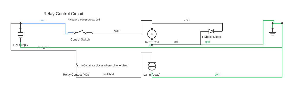
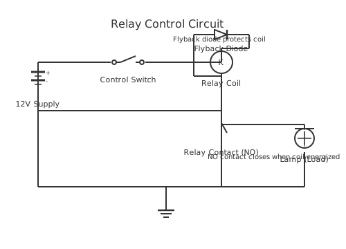
Ladder Diagram Explained — How PLC Logic Really Works — circuit diagram showing component connections+-12V SupplyControl SwitchKRelay CoilFlyback DiodeRelay Contact (NO)Lamp (Load)Relay Control CircuitFlyback diode protects coilNO contact closes when coil energized
Ladder Diagram Explained: How Every Element Works and Why It Was Designed That Way — interactive diagram. Open it in the editor to customise components and wiring.

This is a free printable ladder diagram explained: download the diagram as SVG or open it and print to paper or PDF.
A ladder diagram is best explained by tracing its lineage: it was invented to let electricians — who already understood relay panels — program the first PLCs without learning a new notation. The result is a graphical language where a software XIC contact looks identical to a drawn NO relay contact, and a software OTE coil looks identical to a drawn contactor coil symbol. Understanding this relay-panel heritage explains every design choice in the language, including the NC stop-button convention, the seal-in circuit, and even why the language is called 'ladder' in the first place.

## Ladder Diagram Explained From First Principles

To explain a ladder diagram from the ground up, start with a physical relay panel from 1960. The panel contains a 24V DC control circuit. To start a motor, an operator presses a momentary START pushbutton (NO), which completes the circuit and energises the contactor coil KM1. KM1's main contacts close, applying three-phase power to the motor. An auxiliary contact of KM1 wires in parallel with the START pushbutton — this holds the contactor coil energised after the button is released. The STOP pushbutton, wired in series, is NC: normally the circuit is complete through it, but pressing it breaks the circuit and de-energises the coil. The overload relay contact OL is also NC in series — when the motor overloads, the OL trips and breaks the circuit.

Now replace every physical component with a software equivalent: the START pushbutton becomes an XIC contact on the PLC's input I:0/0 bit. The auxiliary contact seal-in becomes an XIC contact on the output O:0/0 bit. The STOP becomes an XIC contact on input I:0/1 (which is bit=1 at rest because the NC button closes the field circuit). The OL contact becomes another XIC on I:0/2. The contactor coil KM1 becomes an OTE coil on output O:0/0, which drives the physical output terminal, which actually energises the contactor coil.

The result is one ladder rung: [XIC I:0/0 || XIC O:0/0] — XIC I:0/1 — XIC I:0/2 — OTE O:0/0. This rung is functionally identical to the relay circuit. The PLC reads the input bits, evaluates the boolean equation, and writes the result to the output terminal — 1,000 times per second. The physical relay panel is now software, but the logic and the symbol language are the same.

## How Each Element of a Ladder Diagram Works

**Left power rail:** Represents the positive supply in the logical circuit. Every rung starts from here. It is always TRUE. Think of it as the live conductor in the relay schematic — everything to its right is downstream of the supply.

**Right power rail:** The return. Every rung ends here. An output coil connected to the right rail is 'energised' when the rung to its left is TRUE. The rail itself carries no current — it is a visual convention.

**XIC contact (-| |-):** The software equivalent of a normally-open relay contact. The contact examines the bit in the PLC's data table: if bit=1 (the associated input is active or the referenced output is energised), the contact passes. If bit=0, the contact blocks. This is called 'Examine If Closed' because it asks: 'Is the switch closed (bit=1)?'

**XIO contact (-|/|-):** The software equivalent of a normally-closed relay contact. 'Examine If Open' — it asks: 'Is the switch open (bit=0)?' Passes when bit=0, blocks when bit=1. Used for interlock conditions, fault flags, and E-stop contacts (where the physical NC wiring makes the bit=1 at rest, and the XIC — not XIO — passes current through the rung while the button is not pressed).

**OTE coil (-( )-):** The software equivalent of the relay coil. When the rung evaluates TRUE, the OTE sets its bit to 1, which drives the physical output terminal high (usually 24V DC or 120V AC, depending on the output module). When the rung is FALSE, the bit clears to 0 and the output de-energises. This is non-retentive — it faithfully follows the rung state every scan.

**OTL/OTU coils (SET/RESET):** The software equivalent of a self-latching relay. OTL sets the bit once and holds it — like physically wiring a mechanical latch to a relay armature. OTU resets it. Used when an output must stay active after its command signal disappears — for example, a cycle-started flag, a fault alarm, or a batch-complete indicator.

**TON (Timer On Delay):** The software equivalent of a pneumatic or electronic on-delay timer relay. The EN (enable) input is the rung condition. While EN is TRUE, the ACC (accumulated) value increments. When ACC ≥ PRE (preset), the DN (done) bit sets, which can be used as an XIC contact downstream. If EN goes FALSE before ACC reaches PRE, the timer resets to zero — like a spring-return timer.

**CTU (Count Up):** The software equivalent of an electromechanical pulse counter. Each FALSE-to-TRUE transition of the enable rung increments ACC. When ACC ≥ PRE, the DN bit sets.

## The Scan Cycle Explained Step by Step

The PLC scan cycle is the engine that makes the software relay panel work. Without understanding it, seemingly correct programs will produce mysterious failures.

**Step 1 — Input scan:** At the start of each scan, the PLC reads every physical input terminal — thousands of discrete and analog channels — and writes the states to the Input Image Table (a block of RAM). This snapshot is then frozen. Changes to physical inputs after this point are ignored until the next scan.

**Step 2 — Program scan:** The PLC evaluates every rung from top to bottom, left to right. For each XIC contact, it looks up the bit in the appropriate image table: if the bit corresponds to a physical input, it looks in the Input Image Table. If it corresponds to an internal bit (B3:0/0) or an output (O:0/0) that was set earlier in the same scan, it looks in the Output/Data Table, which already reflects changes from earlier rungs. This means the evaluation order of rungs matters for state-machine logic.

**Step 3 — Output scan:** The Output Image Table is pushed out to the physical output terminals.

**Step 4 — Housekeeping:** System diagnostics, Ethernet/serial communications, and deferred tasks.

Practical implication of scan time: If a PLC scans in 10 ms and a machine produces parts at 10 per second (one part every 100 ms), the photosensor signal will be present for 100 ms — ten scan cycles. The counter will increment correctly because each high-to-low transition takes at least one full scan. But if the machine runs at 200 Hz (5 ms per part), each part's signal may be shorter than one scan and will be missed. The solution is a hardware high-speed counter (HSC) input module that counts pulses in hardware independently of the scan cycle.

## Why the NC Stop Button Is the Most Explained Concept in PLC Training

The NC (normally-closed) stop button is one of the most important — and most misunderstood — concepts in industrial PLC programming, and it deserves a careful explanation.

The principle is called fail-safe wiring: design the circuit so that a hardware failure (broken wire, unpowered device, failed sensor) produces the safe machine state (stopped, de-energised, valves closed). Consider two designs:

**Design A (unsafe — NO Stop button wired to PLC input):** Wire breaks → input module reads no current → bit = 0 → XIC Stop contact opens → motor stops. This looks safe. But now consider: the operator presses Stop. Button opens circuit. Bit = 0. XIC opens. Motor stops. Good. What happens if you use XIO instead of XIC for this stop contact? Wire breaks → bit = 0 → XIO is TRUE → motor can run, cannot be stopped. This is catastrophically dangerous.

**Design B (correct — NC Stop button wired to PLC input):** At rest (not pressed): NC field circuit closed → bit = 1 → XIC passes → motor can run. Wire breaks: circuit opens → bit = 0 → XIC opens → motor stops — safe outcome. Stop pressed: NC contact opens field circuit → bit = 0 → XIC opens → motor stops — correct operation. Fault in the PLC (bit stuck at 0): XIC open → motor stops — safe.

In Design B, every hardware fault mode results in the motor stopping. This is the definition of fail-safe. The NC wiring at the hardware level is what provides this safety property — not the choice of XIC vs XIO symbol in the ladder. The IEC 60204-1 standard mandates NC wiring for machine stop functions for exactly this reason.

## Ladder Diagram vs Relay Schematic: Direct Comparison

The following comparison shows how every element of a relay panel circuit maps directly to a ladder diagram symbol:

NO pushbutton (physically wired, closes when pressed) → XIC contact on the input bit corresponding to that terminal.

NC pushbutton (physically wired, opens when pressed) → XIC contact on the NC input bit (bit=1 at rest; opens when pressed).

NO auxiliary contact of a motor contactor → XIC contact on the output bit driving that contactor coil.

NC thermal overload relay contact → XIC contact on the NC-wired OL input (bit=1 when healthy; opens when tripped).

Contactor coil → OTE coil on the output bit connected to the contactor coil terminal.

Timer relay (on-delay) → TON instruction block on the enable rung.

Timer relay auxiliary contact (done) → XIC contact on the timer's DN bit.

The visual symbol language is the same; the execution mechanism is different — but for a maintenance electrician holding a wiring diagram in one hand and a PLC printout in the other, the logic is immediately readable.

## IEC 61131-3 and the Five PLC Languages

Ladder Diagram (LD) is one of five programming languages standardised by IEC 61131-3, the international standard for PLC programming. The others are: Structured Text (ST, Pascal-inspired text language), Function Block Diagram (FBD, data-flow graphical language), Sequential Function Chart (SFC, state-machine language), and Instruction List (IL, deprecated assembly-style language). IEC 61131-3 ensures that LD programs follow the same logical rules regardless of the PLC manufacturer — a Siemens TIA Portal LAD program and an Allen-Bradley Studio 5000 ladder program implement the same boolean operations with the same symbol meanings, differing only in address format and software environment.

## How Ladder Diagrams Are Used Across Industries

Ladder diagram programming is found in virtually every industry where automated machinery operates: automotive (press lines, robot cell interlocks, conveyor systems), food and beverage (filling, sealing, coding, packing), pharmaceuticals (sterilisation validation, dosing sequences), water and wastewater (pump station control, chemical dosing, level control), oil and gas (wellhead shutdown, pipeline isolation valve control), HVAC and building automation (fan coil unit scheduling, chiller control), and mining (conveyor protection, ventilation fan control). The language's longevity across these industries — now over 50 years — is a direct consequence of its readability by both software-trained programmers and field-service electricians who never wrote a line of code.

Practise these concepts immediately — circuitdiagrammaker's free browser-based ladder editor lets you draw rungs with XIC, XIO, OTE, and timer blocks, then export a clean SVG or PDF diagram for your study notes or engineering documentation.

How to wire ladder diagram explained

  1. Trace the relay panel origin of each symbol For each ladder symbol, identify its physical relay panel counterpart: XIC = NO relay contact, XIO = NC relay contact, OTE = relay coil, TON = on-delay timer relay. Understanding the physical origin makes the symbol conventions intuitive rather than arbitrary.
  2. Read a rung as a sentence Translate each rung into plain English: 'If Start is pressed (XIC I:0/0) OR Motor is already running (XIC O:0/0), AND Stop is not pressed (XIC I:0/1 where I:0/1=1 at rest), AND overload is healthy (XIC I:0/2), THEN run the motor (OTE O:0/0).' This sentence-translation skill is the core of reading any industrial ladder program.
  3. Identify the scan order impact In a multi-rung program, deliberately place an output coil (OTE B3:0/0) on Rung 1 and an XIC contact on that same bit on Rung 2. In simulation, observe that Rung 2 sees the updated bit value from Rung 1 within the same scan. Then reverse the rungs (Rung 2 now sets B3:0/0, Rung 1 reads it) and observe that Rung 1 now sees the OLD value — one scan delay. This demonstrates how rung order affects inter-rung timing.
  4. Explain the NC Stop button to a colleague The best way to fully understand the NC Stop button principle is to explain it aloud: describe what happens to bit I:0/1 in each scenario (not pressed, pressed, wire broken) and what the XIC contact does in each case. If you can explain all three scenarios correctly, you understand it. If not, re-read the fail-safe section above.
  5. Compare a relay schematic drawing to its equivalent ladder rung Find or draw a simple relay motor control schematic (START NO, STOP NC, OL NC, contactor coil in series). Write the equivalent ladder rung using XIC, XIC, XIC, OTE plus a seal-in parallel branch. Verify the logical equivalence by tracing both circuits under the same input conditions.
  6. Identify all output interactions in a multi-rung program Use the cross-reference function in your programming software to find every rung that reads or writes a given bit. For a motor output O:0/0, the cross-reference should show: Rung 1 writes it (OTE), Rung 1 reads it (XIC seal-in branch), possibly Rung 3 reads it (TOF timer enable). Any rung that writes the same output not shown here is a duplicate-coil bug.

Specifications

XIC — Examine If ClosedNormally-open contact (-| |-). Bit=0: FALSE (blocks). Bit=1: TRUE (passes). Allen-Bradley name. IEC equivalent: normally-open contact symbol.
XIO — Examine If OpenNormally-closed contact (-|/|-). Bit=0: TRUE (passes). Bit=1: FALSE (blocks). Allen-Bradley name. IEC equivalent: normally-closed contact symbol.
OTE — Output EnergizeNon-retentive output coil (-( )-). Rung FALSE: bit=0. Rung TRUE: bit=1. Bit follows rung state exactly each scan.
OTL — Output LatchSET coil (-(L)-). Rung TRUE: sets bit=1, retains 1 when rung goes FALSE. Must be paired with OTU to clear.
OTU — Output UnlatchRESET coil (-(U)-). Rung TRUE: clears bit=0.
TON — Timer On DelayOn-delay timer block. EN: enable bit (rung state). ACC: accumulated ms. PRE: preset ms. TT: timing bit. DN: done bit (ACC≥PRE). Resets when EN=FALSE.
TOF — Timer Off DelayOff-delay timer block. DN=1 immediately when EN=TRUE. Starts timing when EN=FALSE. DN=0 when ACC≥PRE.
CTU — Count UpUp-counter. Increments ACC on each FALSE→TRUE rung transition. DN=1 when ACC≥PRE. Requires RES to reset.
Seal-in contactXIC contact referencing the output coil's own bit, placed in parallel with the Start input. Holds the rung TRUE after the momentary Start button is released.
Interlock contactXIO contact referencing a competing output bit, placed in series on a rung. Prevents both outputs from energising simultaneously. Required on every forward/reverse motor circuit.
Fail-safe wiringPrinciple: wire Stop buttons, E-stops, and guard contacts NC at hardware level so a broken wire produces bit=0, which opens any XIC contact, putting the machine in a safe (stopped) state.
Scan cycleInput Scan → Program Scan → Output Scan → Housekeeping. Typical: 1–20 ms. Maximum reliable input signal width = 1 scan time minimum.

Safety warnings

Tools needed

Common mistakes

Troubleshooting

Motor contactor drops out unexpectedly mid-cycle
Cause: The seal-in rung goes FALSE due to an intermittent input (bit flickering between 0 and 1 faster than expected), or the output module is overloaded and the output driver is dropping out. Fix: Monitor the rung in real time during the fault. Watch for any contact that flickers FALSE. If all contacts appear TRUE but the output drops, check the output module fault status and the physical output circuit (wiring, fuse, contactor coil resistance).
PLC program logic is correct but the machine does not behave as programmed
Cause: The I/O allocation table has an error — a physical input is connected to the wrong terminal, so the PLC is reading the wrong signal, or an output is driving the wrong device. Fix: Force each input bit ON individually and physically observe which field device activates. Compare against the I/O table. If a forced output bit doesn't match the expected field device, correct the wiring or the address in the program.

Frequently asked questions

What is a ladder diagram in simple terms?

A ladder diagram is a graphical programming language for PLCs that looks like a ladder. The two vertical sides are power rails; the horizontal rungs contain logic. Each rung is a boolean condition: if the conditions on the left evaluate to TRUE, the output on the right activates. It was designed to look like the relay-logic wiring diagrams that electricians already used, making it the most accessible PLC programming language for electrical technicians.

What is ladder logic explained for beginners?

Ladder logic is a way to write machine control programs that looks like electrical circuit drawings. Instead of physical switches and relay coils, you use software symbols on a computer screen. An XIC symbol (-| |-) represents a switch that is ON when its signal is active. An OTE symbol -( )- represents a device (motor, light, valve) that activates when the logic path to it is complete. The PLC reads all the inputs, evaluates all the rungs, and updates all the outputs — 1,000 times per second.

What does XIC mean in a ladder diagram?

XIC stands for Examine If Closed — it is the normally-open (NO) contact instruction in Allen-Bradley ladder logic. It examines whether its associated data bit is 1 (closed/active) and passes logical current if it is. In Siemens TIA Portal the equivalent symbol is a normally-open contact drawn identically. In plain language: XIC asks 'Is this condition TRUE right now?'

What does XIO mean in a ladder diagram?

XIO stands for Examine If Open — it is the normally-closed (NC) contact instruction. It examines whether its associated bit is 0 (open/inactive) and passes logical current if it is. In plain language: XIO asks 'Is this condition NOT active right now?' Used for fault interlocks, mutual exclusion between competing outputs, and any condition where the output should be blocked when a specific event occurs.

How does a PLC ladder diagram work?

A PLC ladder program executes in a continuous loop: (1) the PLC reads all physical inputs into memory, (2) evaluates every rung top-to-bottom using boolean logic, (3) writes output results to physical output terminals, then repeats. Each rung is a boolean equation: contacts (conditions) and output coil (result). If the conditions evaluate TRUE, the output energises. The loop runs 50–1,000 times per second, making the PLC appear to respond instantaneously to real-world inputs.

What is the difference between a ladder diagram and a circuit diagram?

A circuit diagram (schematic) shows the actual electrical connections — conductors, component values, terminal numbers, and power supply levels. A ladder diagram shows the logical control program — the software boolean equations that determine when outputs activate. A complete machine has both: the circuit diagram for electricians building the panel, and the ladder diagram for the PLC program inside it. The two documents should agree: every input shown in the circuit diagram should appear in the I/O allocation table used to write the ladder program.

Why do we use ladder logic for PLC programming?

Ladder logic is used because it is readable by both programmers and maintenance electricians without requiring either group to learn an unfamiliar notation. Programmers recognise boolean logic; electricians recognise the relay schematic symbols. This dual readability reduces training costs and improves troubleshooting speed on the plant floor. It is also standardised by IEC 61131-3, meaning the same skill transfers across virtually all PLC brands.

Can you explain the seal-in contact in a ladder diagram?

The seal-in contact (also called hold-in or latch contact) is a normally-open contact wired in parallel with the Start button and controlled by the output coil itself. When Start is pressed and the output energises, the output's own XIC contact closes in parallel, providing a second path for current. When the momentary Start button is released, the seal-in contact maintains the current path — the output holds itself ON. This is how a momentary pushbutton latches an output without requiring a latching (OTL) instruction.

Related diagrams

Free electrical calculators

Edit this diagram free in the online editor