Light Wiring Diagram: Switch, Fixture and Circuit Connections for Residential Lighting
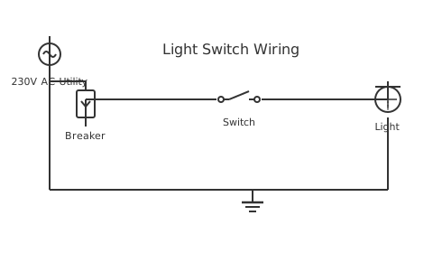
This is a free printable light wiring diagram: download the diagram as SVG or open it and print to paper or PDF.
A light wiring diagram shows how to connect a light switch and fixture to a branch circuit, routing the hot conductor through the switch leg and neutral directly to the fixture to enable safe, code-compliant switching of residential lighting loads.
Diagram checks and scope
- Components
- 5
- Wired connections
- 5
- Automated check
- Automated pin, route, source, and topology checks passed; this is not a safety certification.
A basic residential lighting circuit begins at the panel where a 15 A breaker protects a circuit of 14 AWG NM-B cable. The breaker connects the black hot conductor to the 120 V bus and the white neutral connects to the neutral bar. From the panel, the cable runs to the first device — which may be a switch box or a fixture box depending on how the house was wired. In switch-loop or switch-leg wiring, the cable first reaches the light fixture box where neutral is distributed to the fixture, and the switched hot arrives from the switch after the hot travels down to the switch and back to the fixture via a two-wire cable called a switch leg. The white wire in the switch leg cable carries the unswitched hot down to the switch and must be re-identified with black tape at both ends per NEC 200.7. The black wire in the switch leg carries the switched hot back from the switch to the fixture. In power-at-switch wiring, supply power arrives at the switch box first. The hot connects to the switch, the switched hot leaves the switch and travels to the fixture, and the neutral bypasses the switch, also running to the fixture in the same 14/2 cable. This method is now required by NEC 404.2(C) which mandates a neutral conductor in every switch box. Connecting the fixture itself requires matching the black wire from the switch to the fixture hot terminal — usually identified by the brass-coloured shell or the wire connected to the centre contact of the lamp socket. The white neutral connects to the fixture neutral terminal — typically identified by the silver shell, the outer threaded shell of the lamp socket. The ground connects to the green screw on the fixture and bonds to the metal box. Overcurrent protection sizing follows conductor ampacity: 14 AWG is limited to 15 A breakers and 12 AWG to 20 A breakers — never upsize a breaker beyond the conductor ampacity as the wire is the protected element.
How to wire light wiring diagram
- Plan the circuit layout Determine whether power arrives at the switch box or fixture box. This determines cable routing. New construction must include neutral at the switch box. Sketch the layout showing cable runs and junction box locations.
- Run cable and install boxes Install listed electrical boxes rated for the fixture weight and conductor fill. Run NM-B cable through wall cavities, securing every 1.2 m and within 300 mm of every box. Leave 150 mm of conductor extending from each box.
- Wire the switch Connect hot to one switch terminal and the switched hot (black of switch-leg cable) to the other terminal. Connect neutral to the neutral connector in the box (not to the switch). Connect ground to the switch ground screw.
- Wire the fixture At the fixture box, connect switched hot (black) to the fixture black wire. Connect neutral (white) to the fixture white wire. Connect ground to the fixture ground lead and to the metal box. Secure the fixture to the mounting bracket.
- Test and commission Restore power at the breaker. Verify the switch controls the fixture correctly. Measure voltage at the fixture with the switch on — should be within 5 percent of supply voltage. Check fixture temperature after 15 minutes of operation.
Specifications
| Circuit conductor size | 14 AWG (15 A circuit) or 12 AWG (20 A circuit) |
|---|---|
| Maximum continuous load | 80% of breaker rating: 12 A (15 A) or 16 A (20 A) |
| Switch type (basic) | Single-pole single-throw (SPST), 15 A or 20 A rated |
| Fixture box weight rating | Marked on box — minimum 22 kg for heavy fixtures |
Safety warnings
- The white wire in a switch-leg cable carries unswitched hot current and is energised even when the switch is off — never assume a white wire is neutral without testing.
- Always cap unused wires with wire nuts and tuck them safely into the box — exposed conductors in lighting boxes cause arcing and fire over time.
- Verify the fixture wattage does not exceed the outlet box rating — boxes are marked with maximum wattage and the weight of the fixture they can support.
Tools needed
- Non-contact voltage tester for verifying all conductors before touching
- Wire strippers and electrician's pliers for conductor preparation
- Wire nuts in appropriate sizes for the conductor count and gauge
- Digital multimeter for switch continuity verification before fixture installation
Common mistakes
- Connecting the neutral wire to the switch, which leaves the fixture hot at all times and only switches the neutral — a serious shock hazard.
- Using a 20 A breaker on a 14 AWG circuit because the 15 A breaker kept tripping, bypassing the overcurrent protection the conductor requires.
- Making wire connections outside the junction box without using a listed connector, violating NEC 300.15 which requires all splices be in accessible boxes.
Troubleshooting
- Light flickers when dimmed
- Cause: Dimmer incompatible with LED driver or load below dimmer minimum Fix: Replace dimmer with an LED-rated dimmer from the same manufacturer as the fixture, or check the fixture's compatible dimmer list. Verify the total LED wattage exceeds the dimmer's minimum load rating.
- Breaker trips when light is switched on
- Cause: Short circuit in fixture wiring or inrush current from many LED drivers Fix: Disconnect the fixture and test the circuit with no load. If breaker holds, the fixture has an internal short — replace the fixture. If the breaker trips with many LED fixtures, verify the total inrush current is within breaker rating.
- Light works but switch does not turn it completely off
- Cause: Dimmer with no neutral creating ghost voltage through LED driver Fix: Install a proper neutral wire at the switch box per NEC 404.2(C). Replace the dimmer with a neutral-required model that uses both hot and neutral for its electronics instead of borrowing current through the LED driver.
Frequently asked questions
Why must the switch interrupt the hot wire and not the neutral?
NEC 404.2(B) requires single-pole switches to interrupt only the ungrounded (hot) conductor. If the switch interrupts the neutral instead, the fixture's screw shell and internal wiring remain energised even when the switch is off. Anyone changing a lamp with the switch off would contact live metal and receive an electric shock. Interrupting the hot ensures the fixture is completely de-energised when the switch is open.
What is a switch leg and how does it differ from a switch loop?
The terms are often used interchangeably but have slightly different meanings. A switch leg is the cable run between the switch and the fixture, carrying the switched hot from switch to fixture. A switch loop traditionally refers to the configuration where both the hot-down and switched-hot-up wires run in the same two-wire cable to a switch, forming a loop from the fixture box to the switch and back. NEC now requires neutral in every switch box, making traditional switch loops non-compliant for new construction.
How many lights can I put on a 15 A circuit?
A 15 A circuit can supply a maximum continuous load of 12 A (80 percent of 15 A for continuous loads). Standard incandescent bulbs are being replaced by LED equivalents that draw approximately 10 W each. At 120 V, 10 W LED draws 0.083 A. At the 12 A limit, you could theoretically connect 144 LED fixtures. In practice, lighting circuits also serve outlets and the NEC limits the number of outlets on a circuit through load calculation methods in NEC Article 220.
What does a dimmer switch require compared to a standard switch?
A dimmer switch requires a neutral wire in the switch box to power its electronic phase-cutting circuitry, which is why NEC now mandates neutral in all switch boxes. Dimmers must be matched to the load type — LED dimmers specifically designed for LED drivers, not incandescent dimmers, should be used with LED fixtures to prevent flicker and buzzing. Check that the dimmer's minimum load rating is met by the connected LED fixtures.
Can I add more lights to an existing circuit?
Yes, provided the circuit has remaining capacity. Calculate the existing load in watts and subtract from the circuit capacity (1440 W for a 15 A circuit at 80 percent continuous load factor). The difference is available for additional fixtures. Also verify the circuit wiring can accommodate additional connections — boxes must have sufficient fill volume per NEC Table 314.16 for the wire count.
Sources and verification
Review status: Not independently reviewed. Automated topology checks confirm stored terminals and routes, not the correctness of manufacturer pin assignments, ratings, regional codes, or installation decisions. Verify those claims against the current primary documentation before use.
- IEC 61082-1:2014 — Rules for electrotechnical documents — International Electrotechnical Commission. Supports: General diagram, drawing, table, and reference-designation presentation conventions. Checked 2026-07-15.
Related diagrams
- 3 wire motion sensor light wiring diagram
- eaton light switch wiring diagram
- light sensor circuit diagram
- motion sensor light switch wiring diagram
- motion sensor light wiring diagram
- trailer light wiring diagram 4 pin