How to Install and Wire Single phase induction motor wiring diagram
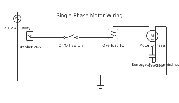
This is a free printable single phase induction motor wiring diagram: download the diagram as SVG or open it and print to paper or PDF.
This comprehensive guide covers proper installation procedures, wiring methodologies, and safety considerations for single phase induction motor wiring diagram systems. Learn correct component selection, circuit configuration, and testing procedures ensuring reliable operation.
Diagram checks and scope
- Components
- 7
- Wired connections
- 8
- Automated check
- Automated pin, route, source, and topology checks passed; this is not a safety certification.
Single-phase induction motors provide economical motor control solutions for residential and light commercial applications requiring variable speed operation without complex control circuitry. The motor design incorporates two stator windings at 90-degree electrical angles: the main running winding and an auxiliary starting winding. During motor starting, the starting capacitor creates phase displacement between windings, producing rotating magnetic field necessary for motor torque development. As motor speed increases toward synchronous speed, centrifugal switches automatically disconnect the starting circuit and capacitor. Thermal overload protection responds to sustained overcurrent conditions that indicate stalled rotor or excessive load conditions. Run capacitors improve operating efficiency and power factor by maintaining phase displacement during normal operation. Bearing lubrication through sealed bearings or oil-saturated porous sleeves extends motor life without maintenance. Temperature rise limitations based on insulation class determine continuous duty rating and intermittent peak power capability. Mechanical vibration should remain minimal with proper mounting and rotor balance. Regenerative braking is not possible with standard induction motor designs.
How to wire single phase induction motor wiring diagram
- Verify motor nameplate voltage matches available supply voltage and confirm supply frequency compatibility
- Install circuit breaker or fuse sized appropriately for motor full-load current at 125-150% rating
- Connect motor leads to supply through proper control switching and protective devices
- Verify motor rotation direction by brief operation and reverse any two leads if rotation is incorrect
- Test starting torque by acceleration time observation and confirm motor reaches full speed within reasonable duration
- Monitor motor temperature during initial operation and verify thermal overload protection responds to sustained overload
Frequently asked questions
What distinguishes single-phase from three-phase induction motors?
Single-phase motors require starting capacitors to create initial rotating magnetic field, while three-phase motors generate rotating field directly from three 120-degree phase-shifted supply voltages.
Why do single-phase motors require starting capacitors?
Starting capacitors create phase displacement between the main and auxiliary windings, producing the rotating magnetic field necessary to generate starting torque.
How does speed control work in single-phase induction motors?
Speed varies with load and supply voltage. Electronic speed controllers using triac circuits adjust voltage to modify motor speed, with modern designs providing smooth variable-speed operation.
What causes single-phase motor humming without rotation?
Motor humming typically indicates failed starting capacitor preventing proper phase displacement, open starting winding, or mechanical binding preventing rotor rotation.
How should single-phase motor circuits be protected?
Circuit breakers or fuses sized at 125-150% of motor full-load current, combined with thermal overload protection, prevent damage from sustained overcurrent conditions.
Sources and verification
Review status: Not independently reviewed. Automated topology checks confirm stored terminals and routes, not the correctness of manufacturer pin assignments, ratings, regional codes, or installation decisions. Verify those claims against the current primary documentation before use.
- IEC 61082-1:2014 — Rules for electrotechnical documents — International Electrotechnical Commission. Supports: General diagram, drawing, table, and reference-designation presentation conventions. Checked 2026-07-15.
Related diagrams
- 220v single phase motor wiring diagram
- 3 phase induction motor diagram
- 3 phase motor to single phase wiring diagram
- 3 wire single phase motor connection
- 4 lead single phase motor wiring diagram
- 6 lead single phase motor wiring diagram with capacitor