Starter Relay Wiring Diagram
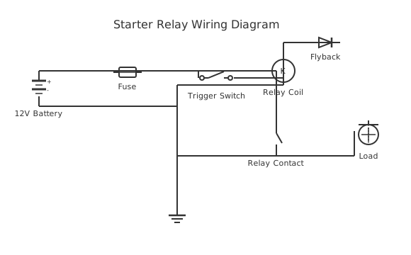
This is a free printable starter relay wiring diagram: download the diagram as SVG or open it and print to paper or PDF.
A starter relay routes high current from the battery to the starter motor when the ignition key is turned. This guide shows correct wiring, pin identification, and troubleshooting steps.
Diagram checks and scope
- Components
- 8
- Wired connections
- 10
- Automated check
- Automated pin, route, source, and topology checks passed; this is not a safety certification.
The starter relay acts as an electrically controlled switch that allows a small ignition-circuit current (5-10 A) to trigger a high-current path (up to 200 A) to the starter motor. Without this relay the ignition switch would need to carry destructive current and would fail rapidly. In a typical automotive system the battery positive terminal connects to the relay power pin (terminal 30 or B+). The ignition switch feeds the relay coil via the control pin (terminal 85 or S). When the key is turned to START, current flows through the coil, generating a magnetic field that closes the internal contacts. These contacts complete the heavy-gauge cable from terminal 30 to the output pin (terminal 87 or M), which powers the starter motor solenoid. Terminal 86 (or ground) returns the coil current to chassis ground. Older vehicles with solenoid-mounted starters may integrate the relay function inside the solenoid itself. Four-pin and five-pin relay variants are both used; the fifth pin (terminal 87a) provides a normally-closed contact not used in basic starter circuits. Selecting the correct relay amperage rating prevents overheating: most starter relays are rated 30-50 A continuous. Wire gauge must match: 10 AWG minimum for control wiring, 4-2 AWG for the main power cable. Corrosion at any terminal can drop voltage below starter threshold and mimic a dead battery. Always test relay function with a multimeter before condemning the starter motor.
How to wire starter relay wiring diagram
- Identify the relay socket Locate the relay panel or in-line relay holder. Use the vehicle wiring diagram or relay cover to match pin numbers: 30 (battery+), 87 (motor out), 85 (ignition trigger), 86 (ground).
- Disconnect battery negative Remove the negative battery cable before making any connections to prevent arcing and accidental starter engagement.
- Run the power feed wire Route a 4 AWG cable from the battery positive post through an in-line 50 A fuse to relay pin 30. Keep the cable away from hot exhaust components.
- Connect control wires Run 16 AWG wire from the ignition switch START terminal to relay pin 85. Connect a 16 AWG wire from relay pin 86 to a clean chassis ground point.
- Wire the output to the starter Run a 4 AWG cable from relay pin 87 to the starter motor solenoid battery terminal. Use a heat-shrink ring terminal for a weatherproof connection.
- Reconnect battery and test Reconnect the negative battery cable. Turn the ignition to START briefly and verify the starter engages. Confirm no abnormal heat at any connection after the test.
Specifications
| Relay coil voltage | 12 VDC |
|---|---|
| Rated contact current | 30-50 A continuous |
| Power feed wire gauge | 4-2 AWG |
| Control wire gauge | 18-16 AWG |
| In-line fuse rating | 50 A (power feed) |
Safety warnings
- Disconnect the negative battery terminal before any wiring work to prevent accidental starter engagement.
- Never work near the starter relay with the ignition in the START position -- unexpected motor spin can cause severe hand injury.
- Ensure all high-current cables (4-2 AWG) have properly rated ring terminals; loose connections arc and cause fires.
Tools needed
- Digital multimeter (voltage and continuity modes)
- Wire stripper and crimping tool for ring terminals
- 10 mm and 13 mm combination wrenches
- Electrical contact cleaner spray
Common mistakes
- Confusing relay pin 85 and 86 -- polarity matters on diode-protected relays; reversing them blows the built-in diode.
- Using undersized wire (18 AWG) for the main battery-to-relay power feed -- this wire will overheat and ignite insulation.
- Skipping the chassis ground connection -- without a solid ground path the relay coil will not engage consistently.
Troubleshooting
- No click when key is turned to START
- Cause: No power reaching relay coil (broken fuse, open ignition circuit, or bad ground) Fix: Probe relay pin 85 with a test light during cranking. If no power, trace back to ignition switch. Check fuse in the ignition circuit.
- Relay clicks but starter does not spin
- Cause: Corroded contacts inside relay or low battery voltage Fix: Measure voltage at relay pin 87 with a multimeter during cranking. If below 10 V, load-test the battery and inspect cable connections for resistance.
- Starter runs continuously after engine starts
- Cause: Relay contacts welded closed Fix: Remove the relay immediately. Replace with a new relay of the correct amperage rating. Check for wiring faults that caused excessive current through contacts.
Frequently asked questions
How do I test a starter relay without removing it?
Apply 12 V directly to the relay coil terminals (85 and 86) while listening for an audible click. Then probe terminals 30 and 87 with a multimeter in continuity mode -- you should read near zero ohms when energised and open circuit when de-energised. This test confirms the relay is switching correctly without disturbing other wiring.
What gauge wire connects the battery to the starter relay?
The battery-to-relay power cable (terminal 30) should be 4 AWG minimum for vehicles with starter motors drawing up to 150 A, and 2 AWG for larger diesel engines up to 200 A. The relay control wires (85/86 to ignition switch and ground) use standard 18-16 AWG automotive wire because they carry only coil current (less than 1 A).
Can a faulty starter relay drain my battery?
Yes. If the relay contacts weld together in the closed position, the starter motor remains energised after the engine starts, drawing hundreds of amps and quickly draining the battery. A fused relay harness protects against this; always include an in-line fuse on the power feed side sized to the relay amperage rating.
Why does my starter relay click but the engine will not crank?
Clicking indicates the relay coil is working but the main contacts may be corroded or the battery voltage is too low to operate the starter motor under load. Check battery voltage under load (should stay above 9.6 V during cranking). Also inspect the large-gauge cable from relay output to starter solenoid for corrosion, breaks, or loose terminals.
Is a starter relay the same as a solenoid?
They perform similar switching functions but are physically different. A solenoid is a multi-function device mounted directly on the starter motor that both engages the pinion gear and connects battery power to the motor armature. A starter relay is a standalone relay elsewhere in the circuit that switches current to the solenoid or directly to the motor input, depending on vehicle design.
Sources and verification
Review status: Not independently reviewed. Automated topology checks confirm stored terminals and routes, not the correctness of manufacturer pin assignments, ratings, regional codes, or installation decisions. Verify those claims against the current primary documentation before use.
- IEC 61082-1:2014 — Rules for electrotechnical documents — International Electrotechnical Commission. Supports: General diagram, drawing, table, and reference-designation presentation conventions. Checked 2026-07-15.
Related diagrams
- 4 pole starter relay wiring diagram
- motorcycle starter relay wiring diagram
- starter motor wiring diagram with relay
- 12v 5 pin relay wiring diagram
- 12v relay pinout
- 4 pin relay wiring