transformer connection diagram
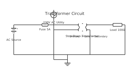
This is a free printable transformer connection diagram: download the diagram as SVG or open it and print to paper or PDF.
Diagram checks and scope
- Components
- 6
- Wired connections
- 8
- Automated check
- Automated pin, route, source, and topology checks passed; this is not a safety certification.
A transformer connection diagram illustrates how primary and secondary windings couple electromagnetic energy in step-up or step-down voltage applications. The diagram shows two coil symbols linked by a magnetic field indicator, demonstrating that transformers transfer electrical power through magnetic induction rather than direct conductor connection. Transformer diagrams distinguish between single-phase and three-phase configurations, with three-phase units displaying three parallel coil pairs representing U, V, and W phases. Connection diagrams specify primary input voltage (typically 480V or 120V industrial supply), secondary output voltage, and kilovolt-ampere (kVA) rating. They include polarity markings (H1, H2, X1, X2) showing lead relationships that determine whether transformers add voltage (series) or provide isolated supplies. Understanding transformer connections prevents mismatched supply voltages that damage loads and ensures compliance with protective grounding and overcurrent device coordination. Industrial environments use transformer diagrams to configure power distribution networks, voltage step-down for control circuits, and isolation for safety-critical systems.
How to wire transformer connection diagram
- Read the transformer nameplate and connection diagram Locate the nameplate on the transformer tank or enclosure. Record the vector group, voltage ratio, kVA rating, impedance percentage, and tap positions. The connection diagram, often printed on the inside of the terminal compartment cover, shows exactly which terminal connects where.
- Verify supply voltage against primary rating Before connecting the primary, confirm the supply voltage matches the transformer rated primary voltage at the selected tap. Applying the wrong supply voltage will either saturate the core, causing overheating, or give incorrect secondary voltage to the connected load.
- Connect the primary terminals Terminate the incoming phase conductors to the correct primary terminals per the connection diagram. For a three-phase transformer, match phases to terminals in the correct sequence. Phase sequence errors can damage downstream equipment sensitive to rotation direction.
- Connect the secondary terminals Terminate the secondary conductors to the secondary terminals per the diagram. Connect neutral to the N terminal. Do not mix up secondary voltages on dual-voltage windings — many transformers have a series/parallel connection option shown on the diagram.
- Establish the earthing connections Earth the transformer tank, neutral terminal, and any required secondary earth points as shown on the connection diagram. Transformer earthing is not optional — it provides the fault current path that allows upstream protection devices to operate correctly during a short circuit.
- Check tap changer position Confirm the tap changer is set to the position matching the actual supply voltage. A 400 V supply on a transformer tapped for 420 V will give a secondary voltage 5% above rated — acceptable for some equipment, damaging for others.
- Commission with secondary disconnected first Energise the transformer with the secondary disconnected and measure the open-circuit secondary voltage. Confirm it matches the rated secondary voltage within 2%. Only then connect the secondary load circuit.
- Monitor under load Under full load, measure primary and secondary voltages and compare to the connection diagram rated values. Measure winding temperature after one hour at full load. Excessive temperature rise indicates an incorrect connection or an overloaded transformer.
Frequently asked questions
What information does a transformer connection diagram show?
A transformer connection diagram shows the primary and secondary winding terminals, their voltage ratings, vector group, tap positions, earthing arrangements, and how the windings connect to the external supply and load circuits. It gives the installer everything needed to correctly terminate and commission the transformer.
What does the vector group on a transformer connection diagram mean?
The vector group describes the winding configuration and phase relationship between primary and secondary voltages. For example, Dyn11 means the primary is delta-connected, secondary is star-connected with neutral, and the secondary voltage leads the primary by 30 degrees. This matters when paralleling transformers.
Can I connect the primary and secondary terminals in any order?
No. Transformer terminals are polarity-marked — dot notation or H1/H2/X1/X2 markings show the correct phase relationship. Reversing connections can cause incorrect voltage polarity, unexpected phase relationships in parallel systems, and potential equipment damage on the secondary circuit.
What does a tap changer on a transformer connection diagram represent?
A tap changer connects to different points on a winding to adjust the turns ratio and therefore the output voltage. Off-circuit tap changers are adjusted with the transformer de-energised. On-load tap changers adjust under load. The connection diagram shows available tap positions and their corresponding voltages.
How do I earth the secondary neutral on a distribution transformer?
On a Dyn11 transformer, connect the secondary neutral terminal (N) to the main earth terminal bar and drive a ground electrode at the transformer if required by the network. The earthing method must comply with SANS 10142-1 Part 2 for LV distribution — an incorrectly earthed neutral causes dangerous touch voltages.
Sources and verification
Review status: Not independently reviewed. Automated topology checks confirm stored terminals and routes, not the correctness of manufacturer pin assignments, ratings, regional codes, or installation decisions. Verify those claims against the current primary documentation before use.
- IEC 61082-1:2014 — Rules for electrotechnical documents — International Electrotechnical Commission. Supports: General diagram, drawing, table, and reference-designation presentation conventions. Checked 2026-07-15.
Related diagrams
- 11kv to 440v transformer diagram
- 120 to 24 volt transformer wiring diagram
- 240v 24v transformer wiring diagram
- 3 phase transformer diagram
- auto transformer diagram
- auto transformer starter diagram