Two Way Switch Connection Diagram — Complete Terminal Reference
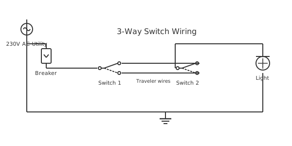
This is a free printable two way switch connection diagram: download the diagram as SVG or open it and print to paper or PDF.
A two-way switch connection diagram maps every terminal of both switches in a two-location lighting circuit, identifying what each conductor connects to and why. This is the definitive installation reference for electricians, DIY homeowners, and maintenance technicians who need to wire, verify, or modify a two-way switching circuit without guessing at connections.
Diagram checks and scope
- Components
- 6
- Wired connections
- 7
- Automated check
- Automated pin, route, source, and topology checks passed; this is not a safety certification.
The two-way switch connection diagram serves as the final verification document for two-location light control installations. Unlike a schematic that shows electrical principles, or a wiring diagram that shows cable routing, a connection diagram maps every specific terminal with its incoming and outgoing conductor — providing terminal-by-terminal installation instructions. For a two-switch lighting circuit, there are exactly twelve conductors to account for: six at Switch 1 (live in, two strap wires out, earth, and neutral passing through), six at Switch 2 (two strap wires in, switched live out, earth, neutral passing through to fitting), plus the connections at the light fitting and consumer unit. Each conductor is assigned a unique wire number in the connection diagram — the same number appears at both ends of every wire, allowing the circuit to be verified by continuity testing without reference to circuit function. At Switch 1, the live (wire 1) connects to the L1/Common terminal. Strap wire A (wire 2) connects from L2 to the L2 terminal of Switch 2. Strap wire B (wire 3) connects from L3 to the L3 terminal of Switch 2. The neutral (wire 4) passes through the switch box without connecting to the switch and continues to the light fitting. The earth (wire 5) connects to the switch earth terminal. At Switch 2, the L2 and L3 terminals receive strap wires 2 and 3 respectively. The switched live (wire 6) exits from the L1/Common terminal and connects to the light fitting live terminal. The neutral (wire 4) arrives from or through the switch box and terminates at the fitting neutral. Earth (wire 5) connects to fitting earth. This systematic numbering approach allows a second person to verify the installation against the connection diagram without needing to understand switching theory.
How to wire two way switch connection diagram
- List all conductors before wiring Count every unique conductor in the circuit. For a two-way switch circuit: live (1), neutral (2), earth (3), strap A (4), strap B (5), switched live (6). Assign a number to each and list them in a table.
- Label both ends of every wire Before routing any cable, fit numbered markers to both ends of every conductor. Use cable tie labels, heat-shrink sleeves with numbers, or permanent marker on white labels. Verify the number is readable after installation.
- Record terminals during wiring As you connect each wire, write down: Device name, Terminal label, Wire number connected. This creates the connection diagram simultaneously with the installation. Do not rely on memory — record as you go.
- Draw the connection diagram Transfer your terminal connection notes into a diagram format. Draw each device with its terminals labeled. Add wire numbers between terminals. Include a wire schedule with color, gauge, and endpoints for each wire number.
- Verify with continuity testing Before energizing, use a multimeter to verify continuity between each pair of terminals connected by the same wire number. All wires should show continuity end-to-end. No unintended continuity should exist between wires of different numbers.
Specifications
| Wire count (two-way circuit) | 6 unique conductors minimum |
|---|---|
| Terminal count per switch | 3 current terminals + earth |
| Strap wires | 2 wires between switch boxes |
| Documentation standard | IEC 61082-4 (connection diagrams) |
Safety warnings
- Verify that wire numbers in your connection diagram match the actual installed wire labels before any test — mismatched labels are worse than no labels as they direct troubleshooting to the wrong location.
- In two-way circuits, the strap wires alternate between carrying live voltage and zero voltage depending on switch position — treat all strap wires as potentially live at all times.
- When modifying an existing two-way circuit, photograph and document all terminal connections before removing any wires — restoring from memory after disconnecting a complex switch circuit is error-prone.
Tools needed
- Multimeter (resistance/continuity function)
- Cable identifier or wire mapper
- Permanent marker for labeling wires
- Approved voltage indicator for live testing
Common mistakes
- Creating a connection diagram from memory after installation rather than documenting during installation — post-installation documentation often contains errors that will mislead future maintenance.
- Assigning the same wire number to two different conductors — each unique conductor in the circuit must have a unique number; never reuse numbers even for wires that appear similar.
- Failing to document the strap wire colors in the connection diagram — two grey wires in a switch box are indistinguishable without documentation of which color goes to which terminal.
Troubleshooting
- Continuity check fails on strap wire A between switches
- Cause: Wire 4 is broken or not terminated at one switch terminal Fix: Probe each switch box for Wire 4 continuity to the other end. The box that shows open circuit is the termination fault. Inspect the terminal — reconnect or replace broken wire.
- Two wire numbers show unexpected continuity to each other
- Cause: Wires 4 and 5 (strap wires) are connected to the same terminal at one switch, or touching inside the conduit Fix: Check both switch boxes for correct terminal assignments. If straps are on different terminals but still showing continuity, inspect the cable run for a fault — possible insulation damage.
- Connection diagram shows wire at L1 of Switch 2 but no voltage there when switch should be on
- Cause: Wire number at Switch 2 L1 is incorrectly labeled — actual wire is strap wire not switched live Fix: Re-ring the wire from Switch 2 L1 to find its actual far end. If it goes to Switch 1 instead of the fitting, the wires are mislabeled. Correct both the labels and the connection diagram to match actual wiring.
Frequently asked questions
How do I number wires in a two-way switch connection diagram?
Assign consecutive integers to each unique conductor starting from the supply. Wire 1 = live supply, Wire 2 = neutral supply, Wire 3 = earth, Wire 4 = strap wire A, Wire 5 = strap wire B, Wire 6 = switched live, and so on. Mark each physical wire with its number at both ends using cable markers or heat-shrink sleeves. The connection diagram then shows: Terminal L1(SW1) ← Wire 1, Terminal L2(SW1) ↔ Wire 4, etc.
What is the difference between a wiring diagram and a connection diagram?
A wiring diagram shows cable routing — where cables physically run through walls, floors, and ceilings. A connection diagram shows terminal connections — what wire number terminates at which terminal of which device, with no reference to physical routing. Both are needed for complete installation documentation. Use the wiring diagram for cable installation and the connection diagram for terminal verification.
How do I verify a two-way switch connection diagram against an installed circuit?
With circuit isolated: use a multimeter in resistance mode to ring out each wire between its documented endpoints. Wire 4 (strap A) should show low resistance between L2 of Switch 1 and L2 of Switch 2. Wire 5 (strap B) between L3 and L3. Wire 1 (live) between MCB and L1 of Switch 1. Wire 6 (switched live) between L1 of Switch 2 and fitting live terminal. Any unexpected resistance indicates a wiring error.
Can a connection diagram be used to diagnose faults without turning the circuit on?
Yes — this is exactly what connection diagrams are designed for. With circuit isolated, use continuity testing to verify each wire pair shown in the diagram. A wire that shows open circuit when the diagram shows it should be continuous has an open fault. A wire that shows continuity to a second terminal not shown in the diagram has a short or unintended connection. This approach locates faults without needing to energize the circuit.
How do I document a two-way switch connection diagram for as-built records?
Draw or print a diagram with a box for each device (Switch 1, Switch 2, Fitting, MCB). In each box, draw the device terminals and write the wire number connected to each terminal. Include a wire schedule table listing each wire number, its color, its source terminal, and its destination terminal. Photograph the open switch boxes before closing them. Store the documents with the property's electrical installation certificate.
Sources and verification
Review status: Not independently reviewed. Automated topology checks confirm stored terminals and routes, not the correctness of manufacturer pin assignments, ratings, regional codes, or installation decisions. Verify those claims against the current primary documentation before use.
- IEC 61082-1:2014 — Rules for electrotechnical documents — International Electrotechnical Commission. Supports: General diagram, drawing, table, and reference-designation presentation conventions. Checked 2026-07-15.
Related diagrams
- two way switch circuit
- wiring two way light switch
- eaton 3 way switch diagram
- legrand 3 way switch
- 1 gang 1 way switch wiring diagram
- 1 gang 2 way switch wiring diagram