Two Way Switch Wiring Diagram Explained
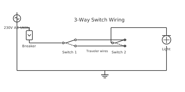
This is a free printable two way switch wiring diagram: download the diagram as SVG or open it and print to paper or PDF.
A two-way switch lets you control one light from two separate locations—top and bottom of a staircase, or either end of a hallway. Understanding the traveler wires and common terminals is essential to wire the circuit safely and correctly.
Diagram checks and scope
- Components
- 6
- Wired connections
- 7
- Automated check
- Automated pin, route, source, and topology checks passed; this is not a safety certification.
A two-way switching circuit uses two SPDT (single-pole double-throw) switches, each with three terminals: a common (COM) terminal and two traveler terminals (L1 and L2). The switches are wired so that toggling either one changes the circuit state—if the light is on, either switch turns it off, and vice versa. The line (hot) conductor from the panel connects to the common terminal of the first switch. Two traveler wires run between the L1 and L2 terminals of both switches, forming alternate current paths. The common terminal of the second switch connects to the light fixture. The neutral conductor from the panel runs directly to the fixture neutral terminal without passing through the switches. When both switch commons connect via the same traveler (both on L1 or both on L2), the circuit is complete and current flows through the lamp. When the travelers cross—one switch on L1 and the other on L2—the circuit is open and the lamp is off. In modern wiring practice, a three-conductor cable (black, red, white) runs between the two switch boxes, with black used as the hot feed, red and white as the two travelers (the white must be re-identified with black tape at both ends if used as a traveler), and a bare or green ground. At each switch box a separate ground wire connects to the switch ground screw. The ground continuity through both switches protects against shock if a wiring fault energizes the switch yoke. Always verify zero voltage at both switch boxes before beginning work, and confirm that the fixture turns on and off from both switch locations before closing the wall boxes. Never use the back-stab (push-in) terminals on switch bodies for traveler wires—use the screw terminals for secure, code-compliant connections that resist loosening under vibration.
How to wire two way switch wiring diagram
- Turn off power and verify Switch off the circuit breaker supplying the switch circuit. Hold a non-contact voltage tester at both switch locations and the fixture to confirm zero voltage before removing any cover plates.
- Identify cable conductors At switch box 1: identify the incoming hot (black from panel), two traveler wires (red and white/re-taped), and bare ground. At switch box 2: identify the two traveler wires, the wire to the fixture, and bare ground.
- Wire switch 1 Connect the hot black wire to the COM (common) screw of switch 1. Connect the red traveler to the L1 screw and the white traveler (marked black) to the L2 screw. Connect bare ground to the green ground screw.
- Wire switch 2 Connect the red traveler to the L1 screw and the white traveler to the L2 screw of switch 2. Connect the wire running to the fixture to the COM screw. Connect bare ground to the green ground screw.
- Wire the fixture Connect the black wire from switch 2 COM to the fixture black (hot). Connect the neutral white wire (run directly from the panel cable) to the fixture white. Connect bare ground to the fixture ground.
- Restore power and test Restore the breaker. Test that toggling either switch changes the light state. Verify the light turns on and off from both locations before installing cover plates.
Specifications
| Switch type | SPDT (3-way) — 15 A / 120–277 VAC |
|---|---|
| Cable required | 14/3 NM-B (15 A circuit) or 12/3 (20 A) |
| Traveler wire count | 2 (red and white/re-identified) |
| Ground connection | Green screw on each switch yoke |
Safety warnings
- Turn off the circuit breaker and verify zero voltage at both switch boxes with a non-contact tester before touching any wiring.
- If the white traveler wire is used as a hot conductor, re-identify it with black electrical tape at both ends to prevent future confusion and NEC compliance.
- Never use back-stab push-in terminals for traveler connections—use screw terminals only to ensure a reliable, vibration-resistant connection.
Tools needed
- Non-contact voltage tester
- Multimeter (continuity mode)
- Flathead and Phillips screwdrivers
- Wire stripper and needle-nose pliers
Common mistakes
- Connecting both traveler wires to the same traveler terminal on one switch—this bypasses the switching logic and the light stays permanently on or off.
- Wiring the neutral through one of the switch boxes instead of running it direct to the fixture—creates a shock hazard when the switch is open.
- Swapping the common terminal with a traveler terminal—the light will work from only one switch location instead of both.
Troubleshooting
- Light stays on regardless of switch position
- Cause: Hot wire connected to a traveler terminal instead of COM on one switch Fix: De-energize, remove switches, and confirm hot feed connects to the COM terminal of switch 1 only.
- Light only controllable from one switch
- Cause: Both traveler wires landed on the same terminal of one switch Fix: Check that red and white travelers connect to L1 and L2 (different terminals) on both switches.
- Switch box has no ground wire
- Cause: Older wiring without equipment ground conductor Fix: Install self-grounding switches or run a new ground wire per NEC 250.130(C) using the panel ground bus.
Frequently asked questions
What is the difference between a two-way and three-way switch?
In North American terminology a "three-way switch" is an SPDT switch used in pairs to control a light from two locations—what the rest of the world calls a two-way switch. The term "three" refers to the three terminals on the switch, not the number of switches. Outside North America, a "two-way switch" is simply an SPST on/off switch, and the two-location circuit uses "intermediate" or "4-way" switches for additional control points.
Can I add a third switch location to a two-way circuit?
Yes—insert a 4-way (DPDT) switch in the traveler path between the two existing 3-way switches. The 4-way switch has four terminals and swaps the two traveler connections when toggled. You can add as many 4-way switches as needed between the two end 3-way switches. Each additional location requires running a 3-conductor cable from the previous switch box to the next.
Why does my two-way switch only work from one location?
This usually means the traveler wires are both connected to the same terminal on one switch, or one traveler wire is connected to the common terminal instead of a traveler terminal. Remove the switches and check that the two traveler wires connect to L1 and L2 (not COM) on each switch. Confirm the hot feed connects to COM on the first switch and the fixture wire connects to COM on the second.
What cable do I need for a two-way switch circuit?
Use 14/3 cable (three conductors plus ground) for a 15-amp circuit, or 12/3 for a 20-amp circuit. The three-conductor cable provides black (hot feed), red and white (travelers), and bare copper (ground). If your existing wiring uses 14/2 cable in both switch boxes with a junction in the ceiling, that older "switch-loop" method is still functional but cannot be converted to smart-switch use without running new cable.
Does it matter which traveler terminal gets which color wire?
No—the two traveler terminals on an SPDT switch are interchangeable. The only terminal assignment that matters is the common (COM) terminal. As long as the same wire connects L1 on both switches and the same wire connects L2 on both switches (without crossing the assignments), the circuit operates correctly. Consistency in color coding makes future troubleshooting much easier.
Sources and verification
Review status: Not independently reviewed. Automated topology checks confirm stored terminals and routes, not the correctness of manufacturer pin assignments, ratings, regional codes, or installation decisions. Verify those claims against the current primary documentation before use.
- IEC 61082-1:2014 — Rules for electrotechnical documents — International Electrotechnical Commission. Supports: General diagram, drawing, table, and reference-designation presentation conventions. Checked 2026-07-15.
Related diagrams
- two way switch circuit
- wiring two way light switch
- eaton 3 way switch diagram
- legrand 3 way switch
- 1 gang 1 way switch wiring diagram
- 1 gang 2 way switch wiring diagram