2 Way Switch Connection Diagram — Every Terminal Identified
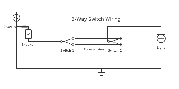
This is a free printable 2 way switch connection diagram: download the diagram as SVG or open it and print to paper or PDF.
A 2-way switch connection diagram focuses on what connects to each specific terminal of both switches — giving installers the precise, terminal-level information needed to wire a two-location light control circuit correctly. Whether using UK or US switch conventions, this guide identifies every screw, labels every wire, and explains what each connection does electrically.
Diagram checks and scope
- Components
- 6
- Wired connections
- 7
- Automated check
- Automated pin, route, source, and topology checks passed; this is not a safety certification.
A 2-way switch connection diagram differs from a general circuit diagram in that it identifies each individual terminal connection rather than just showing overall circuit topology. For a two-switch lighting circuit, six switch terminals must be correctly connected (three per switch), plus the connections at the light fixture and at the supply. Each terminal has a specific electrical role: the common terminal (L1 in UK, COMMON in US) routes the live signal either into or out of the switch depending on the switch's position in the circuit. Traveler/strap terminals (L2, L3 in UK; T1, T2 or TRAVELER in US) are the two alternative paths that the common toggles between. When both switch commons are connected through the same traveler path, the circuit is complete. When they connect through different travelers, the circuit is open. For Switch 1 (supply-side): Terminal 1 (Common/L1) receives the incoming supply live wire — this terminal is always energized when the consumer unit/breaker is on. Terminal 2 (L2/T1) and Terminal 3 (L3/T2) connect to the two strapper/traveler wires running between the switch boxes. For Switch 2 (fixture-side): Terminal 4 (L2/T1) and Terminal 5 (L3/T2) connect to the same two strapper/traveler wires from Switch 1. Terminal 6 (Common/L1) outputs the switched live that feeds the light fixture — this terminal is live only when the switches together complete the circuit. The neutral bypasses both switches and does not connect to any switch terminal. The earth (ground) connects to each switch's earth terminal and to the fixture earth. This terminal-by-terminal breakdown allows any qualified person to wire the circuit correctly by following terminal numbers without needing to understand the switching principle.
How to wire 2 way switch connection diagram
- Mark terminal assignments before wiring Use a permanent marker to label each terminal on both switches before connecting any wires. Write L1, L2, L3 (UK) or COM, T1, T2 (US) clearly on the switch body next to each screw. This prevents confusion during installation.
- Connect supply to Switch 1 common Insert the supply live wire (brown/black) into the L1/Common terminal of Switch 1 and tighten the screw until the wire cannot be pulled out. This is the energized terminal — the most critical connection.
- Connect strap wires between switches Run the first strap wire from L2 of Switch 1 to L2 of Switch 2. Run the second strap wire from L3 of Switch 1 to L3 of Switch 2. Use a consistent color for each strap wire and note the colors.
- Connect switched live from Switch 2 to fixture Connect the switched live wire to the L1/Common terminal of Switch 2. This wire runs to the light fitting line terminal. Mark this wire at the fixture end to identify it as switched live.
- Complete neutral and earth connections Run neutral from supply directly to fixture (no switch connection). Connect earth to both switch earth terminals and to the fixture earth. Test all connections with a tug test before closing switch boxes.
Specifications
| Switch terminals (UK) | L1 (common), L2, L3 + earth |
|---|---|
| Switch terminals (US) | COM, T1 (traveler), T2 (traveler) + ground |
| Strap wire count | 2 wires between the two switches |
| UK switch rating | 6A 230V (domestic) |
Safety warnings
- The supply-side switch common terminal (Terminal 1) is always live when the breaker/MCB is on — de-energize the circuit before connecting or disconnecting this terminal.
- Label all switch terminals with permanent markers during installation — a future electrician must be able to identify each connection without guessing.
- In UK installations, always use earth sleeving on bare earth wires inside switch boxes — unsleeved earth wire can be mistaken for a neutral or live in tight spaces.
Tools needed
- Approved voltage indicator or multimeter
- Flathead screwdriver (insulated)
- Cable markers and permanent marker
- Wire stripper for 1.0-1.5mm² cable
Common mistakes
- Connecting the supply live to the fixture-side switch common instead of the supply-side switch common — the switching order is reversed and the light cannot be controlled from the correct location.
- Using the neutral wire as a strapper wire — the neutral must return current to the supply; using it as a signal wire in the switch loop creates a code violation and potential shock hazard.
- Leaving the strapper wire terminals loose — a partially tightened terminal screw causes intermittent contact that produces arcing, heat, and eventual switch failure.
Troubleshooting
- One strap wire gets hot during operation
- Cause: Both strap wires are connected to the same L2 or L3 terminal at one switch — creating a short between the two traveler paths Fix: Verify each switch has one strap wire on L2 and one on L3. If both straps are on the same terminal, move one to the correct terminal.
- Switch 1 operates light correctly, Switch 2 has no effect
- Cause: Switch 2 common terminal is on an L2/L3 traveler terminal instead of the correct common terminal Fix: Move the fixture wire from the traveler terminal to the correct Common/L1 terminal on Switch 2.
- Intermittent light failure at random times
- Cause: Loose strap wire terminal screw causing intermittent contact Fix: Isolate supply. Inspect all six switch terminals and tighten any that are not fully secure. Give each wire a firm tug — it must not move. Remake connections with fresh wire strip if strands are damaged.
Frequently asked questions
How many terminals does a 2-way switch have and what does each do?
A 2-way switch has three current-carrying terminals plus an earth terminal. The Common (L1) terminal connects to either of the other two terminals depending on switch position — it is the entry/exit point for the live signal. The L2 terminal connects to one strap wire. The L3 terminal connects to the other strap wire. The earth terminal connects to the protective earth conductor and does not carry current in normal operation.
What is a strap wire in a 2-way switching connection?
Strap wires (or traveler wires in US terminology) are the conductors that run between the L2 and L3 terminals of the two switches. There are always two strap wires — one connecting L2 of Switch 1 to L2 of Switch 2, and one connecting L3 of Switch 1 to L3 of Switch 2. These wires carry the live signal between the two switch positions. Only one strap wire carries voltage at any given time depending on Switch 1's position.
Can I use a 2-way switch as a regular on/off switch?
Yes — connect the supply live to the Common (L1) terminal and the switched live to either the L2 or L3 terminal. Leave the remaining L2 or L3 terminal unconnected (or connect to L1 if you want the switch to work in only one direction). The switch functions as a standard SPST on/off switch. This is common practice when replacing a defective 1-way switch with an available 2-way unit.
What happens if I swap the L2 and L3 connections at one switch?
The circuit continues to function correctly as a 2-way control, but the switch positions that give ON versus OFF will be inverted at that location. This is a non-issue functionally but can confuse users if the switches appear to be in different positions for the same light state. Correct by swapping the two strap wires at either switch box.
How do I check my terminal connections without a wiring diagram?
With supply off, use a multimeter in continuity mode. At Switch 1: toggle the switch and verify continuity alternates between Common and L2, then Common and L3. L2 and L3 should never show continuity to each other. At Switch 2: same test. Then ring out each strap wire between Switch 1 and Switch 2 to confirm both are continuous. Finally, verify the neutral runs directly from supply to fixture without passing through either switch.
Sources and verification
Review status: Not independently reviewed. Automated topology checks confirm stored terminals and routes, not the correctness of manufacturer pin assignments, ratings, regional codes, or installation decisions. Verify those claims against the current primary documentation before use.
- IEC 61082-1:2014 — Rules for electrotechnical documents — International Electrotechnical Commission. Supports: General diagram, drawing, table, and reference-designation presentation conventions. Checked 2026-07-15.
Related diagrams
- 1 gang 2 way switch wiring diagram
- 2 gang 1 way switch wiring diagram
- 2 gang 2 way switch wiring diagram
- 2 humbuckers 1 volume 1 tone 3 way switch diagram
- 2 way dimmer switch wiring diagram
- 2 way intermediate switch wiring diagram