2 Way Switch Wiring Diagram — Full Cable Routing & Connections
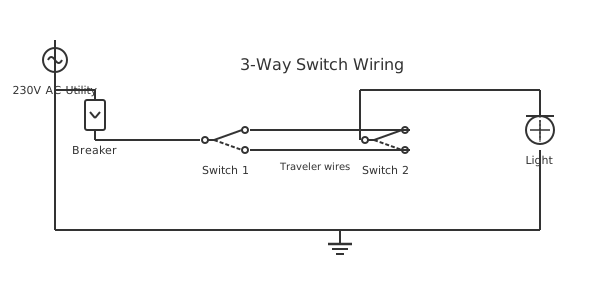
This is a free printable 2 way switch wiring diagram: download the diagram as SVG or open it and print to paper or PDF.
A 2-way switch wiring diagram shows the complete cable routing between consumer unit, first switch, second switch, and light fitting — including which cable goes where, what colors carry which functions, and how to make every connection correctly. This diagram is the practical installation reference used by electricians during first and second fix, covering both the modern harmonised color code and older cable identification.
Diagram checks and scope
- Components
- 6
- Wired connections
- 7
- Automated check
- Automated pin, route, source, and topology checks passed; this is not a safety certification.
Two-way switch wiring requires three cable runs and careful attention to cable type selection. Cable Run 1 brings supply power from the consumer unit to the first switch box: a twin-and-earth cable (2-core + earth) enters the first switch box with the brown conductor as live, blue as neutral (which passes through to the light fitting), and bare copper earth. Cable Run 2 travels between the two switch boxes carrying the strap/traveler wires: this must be a 3-core-and-earth cable (or two separate twin-and-earth cables in some older installations) providing two conductors for the strap wires plus earth. In modern practice, the three-core-and-earth provides brown, black, and grey conductors — brown and grey are used as the two strap wires, black is left as a spare or used for additional functions. In older installations, the three-core provided red, yellow, and blue with bare earth — and the color assignments varied by region and era. Cable Run 3 exits the second switch box to the light fitting: another twin-and-earth cable with the switched live (brown or black-taped white) going to the fitting live terminal and the neutral continuing to the fitting neutral terminal. Key installation detail: the neutral from the consumer unit should ideally run through the switch boxes to the fitting rather than being looped separately, to comply with BS 7671 wiring regulations that require the neutral to accompany its corresponding live conductor in the same cable wherever possible (reduces inductive heating of metal conduit). At each switch box, the correct wires connect to the three terminals of the 2-way switch — live to L1 of Switch 1, strap wires to L2 and L3 of both switches, and switched live from L1 of Switch 2 to the fitting. Earth connects to all metalwork throughout.
How to wire 2 way switch wiring diagram
- Plan and route cables Determine the routing for all three cable runs. Use a cable detector to find existing cables before chasing or drilling. Measure and cut cable lengths with 300mm extra at each termination point.
- Prepare switch boxes Install switch back boxes at both switch locations. Route cables into the boxes through appropriate knockouts, fitting rubber grommets in metal boxes to protect cable insulation.
- Strip and identify all conductors Strip 100mm of outer sheath and 10mm of insulation from each conductor. Apply earth sleeving to bare earth wires. Mark any white or blue wires used as switched live with brown sleeving or permanent marker.
- Wire both switches At Switch 1: supply live → L1, strap wire 1 → L2, strap wire 2 → L3, earth → earth terminal. At Switch 2: strap wire 1 → L2, strap wire 2 → L3, switched live → L1, earth → earth terminal.
- Complete fixture connection and test At the light fitting: switched live → live terminal, neutral → neutral, earth → earth. Restore supply and test 2-way operation from both switch positions.
Specifications
| Supply and fixture cable | 1.0-1.5mm² twin-and-earth (2-core) |
|---|---|
| Between-switch cable | 1.0-1.5mm² three-core-and-earth |
| Installation standard | BS 7671 (UK Wiring Regulations) |
| Maximum circuit load | 6A (1380W at 230V) |
Safety warnings
- Use the correct cable type for each run — 3-core and earth between switches is mandatory; substituting two 2-core cables in the same route is permitted but neutral conductors must still accompany their corresponding lines.
- In older installations, old cable colors (red/yellow/blue) need careful checking — a yellow or blue wire in an older switch box may be a live strap wire, not a neutral or earth.
- Always use cable rated for the circuit current — 1.0mm² for 6A lighting, 1.5mm² for 10A, never less. Check for damage to insulation before installing into walls.
Tools needed
- Cable detector (before drilling or chasing walls)
- Cable stripper for 1.0/1.5mm² twin-and-earth
- Approved voltage indicator
- Multimeter for cable route testing
Common mistakes
- Using 2-core cable between the two switch boxes — the circuit needs three conductors (two straps and earth); 2-core provides only two plus earth, leaving no room for the second strap wire.
- Running the neutral only to the first switch box and not continuing it through to the fitting — the neutral must reach the fitting, not terminate at the switch box.
- Crossing the strap wires accidentally — connecting L2-to-L3 and L3-to-L2 between switches is functionally correct but documents incorrectly; always connect L2-to-L2 and L3-to-L3.
Troubleshooting
- Cable between switch boxes only has two conductors plus earth
- Cause: Wrong cable type was installed — twin-and-earth instead of 3-core-and-earth Fix: The cable must be replaced with 3-core-and-earth. As a temporary workaround (not code compliant), a separate additional wire can be run but should be replaced with proper cable.
- Light flickers when both switches are in the ON position
- Cause: Loose terminal connection on one of the strap wires causing intermittent contact Fix: Isolate circuit. Inspect all terminals at both switch boxes. Re-terminate any loose connections. Ensure stripped wire length is correct and wire is fully inserted before tightening.
- Neutral wire voltage detected at switch box during testing
- Cause: Neutral and live from different phases or circuits crossed somewhere in the cable route Fix: This indicates a wiring error. Isolate all circuits. Verify the neutral in the switch box is from the same cable as the live. A voltage on neutral indicates it is connected to a live source somewhere.
Frequently asked questions
What cable do I need for a 2-way switch circuit?
You need two types: 1.0mm² or 1.5mm² twin-and-earth (2-core + earth) for the supply-to-switch-1 run and for the switch-2-to-fixture run. You need 1.0mm² or 1.5mm² three-core-and-earth (3-core + earth) for the cable running between the two switch boxes to carry the two strap wires plus earth. Do not use a single twin-and-earth for the between-switch run — it does not have enough conductors.
Which way does the cable run between switches affect the wiring?
The cable direction between switches does not matter electrically — both strap wires are symmetrical and carry the same signal roles regardless of cable direction. Connect L2 to L2 and L3 to L3 consistently, or swap both at the same time (connecting L2 to L3 and L3 to L2 at both switches) — neither affects operation. The key is that the two strap wires connect the same-labeled terminals at both switches.
Can the supply cable enter the light fitting instead of the first switch box?
Yes — this is called a "loop at fitting" or "power at fitting" installation. The live from the consumer unit goes to the fitting, a cable runs from the fitting down to Switch 1, another cable between the two switches, and the switched live returns from Switch 2 to the fitting. The switch connections are identical regardless of where the supply enters. The neutral simply stays at the fitting in this configuration.
How much cable should I strip at each switch terminal?
Strip 8-10mm of insulation from the conductor end for UK screwless push-in terminals, or 10-12mm for screw terminals. For the outer sheath of the cable, strip enough to allow the conductors to reach their terminals with a small service loop — typically 75-100mm of sheath inside the switch box. Always fit appropriate cable clamps at the switch box cable entry to protect the cable from strain.
Do I need to notify building control for a 2-way switch installation?
In England and Wales under Part P of the Building Regulations, lighting circuit work in kitchens or bathrooms requires notification. Standard room lighting outside these locations may be self-certified by a Part P-registered electrician or notified to the local authority. Scotland, Wales, and Northern Ireland have slightly different rules. Always check current regulations for your specific location and circuit type before starting work.
Sources and verification
Review status: Not independently reviewed. Automated topology checks confirm stored terminals and routes, not the correctness of manufacturer pin assignments, ratings, regional codes, or installation decisions. Verify those claims against the current primary documentation before use.
- IEC 61082-1:2014 — Rules for electrotechnical documents — International Electrotechnical Commission. Supports: General diagram, drawing, table, and reference-designation presentation conventions. Checked 2026-07-15.
Full written guides
Related diagrams
- 1 gang 2 way switch wiring diagram
- 2 gang 1 way switch wiring diagram
- 2 gang 2 way switch wiring diagram
- 2 humbuckers 1 volume 1 tone 3 way switch diagram
- 2 way dimmer switch wiring diagram
- 2 way intermediate switch wiring diagram