Electrical Wiring Diagram Basics: Standards, Symbols, and Reading Methods

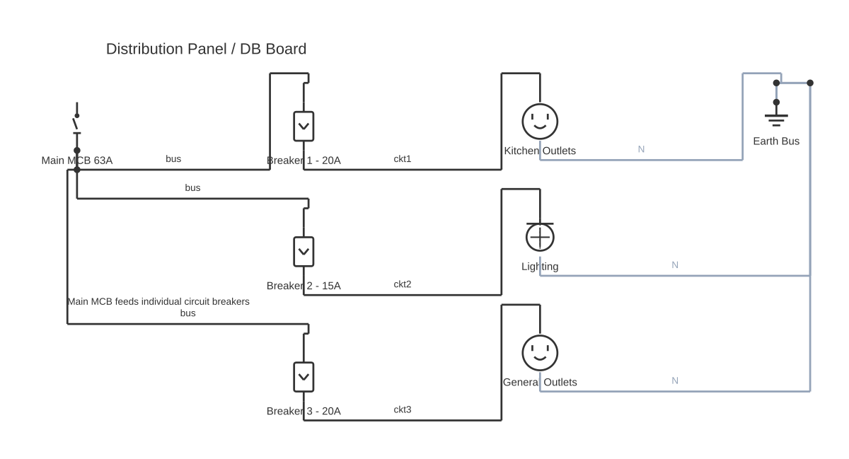
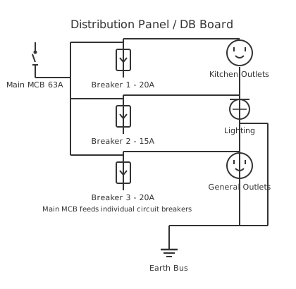
Electrical Wiring Diagram Basics: Full Practical Guide — circuit diagram showing component connectionsMain MCB 63ABreaker 1 - 20ABreaker 2 - 15ABreaker 3 - 20AKitchen OutletsLightingGeneral OutletsEarth BusDistribution Panel / DB BoardMain MCB feeds individual circuit breakers
Electrical Wiring Diagram Basics: Standards, Symbols, and Reading Methods — interactive diagram. Open it in the editor to customise components and wiring.

This is a free printable electrical wiring diagram basics: download the diagram as SVG or open it and print to paper or PDF.
An electrical wiring diagram is the standardised technical drawing that documents every connection, component, and conductor in an electrical system — whether a domestic consumer unit, an industrial motor-control panel, or an automotive harness. Understanding the basics means knowing which diagram type is in front of you, which symbol standard it follows, how to apply the neutral condition rule, and how to trace circuits safely and accurately. This guide covers all of that in one place, with an emphasis on the NEC/NFPA compliance context that most other resources overlook.

The term 'electrical wiring diagram' covers a family of drawing types, not a single format, and choosing the wrong reading method for the diagram in front of you is a very common source of confusion. The six diagram types used in electrical engineering each serve a distinct purpose and require a distinct reading approach.

A schematic diagram uses standardised symbols to show every electrical component and connection, with no regard for physical layout. It emphasises circuit theory and component relationships. A ladder diagram arranges control circuits as horizontal rungs between two vertical power rails — the left rail is typically L1 (live) and the right rail is L2 or neutral. Each rung is an independent logical statement. Ladder diagrams are the dominant format for industrial motor control and PLC programming. A single-line diagram (SLD) represents three-phase systems with a single line per phase to eliminate repetition and show overall power distribution architecture. A block diagram uses boxes connected by arrows to show functional relationships at a system level, without component-level detail. A pictorial diagram shows components as realistic images, useful for homeowners but carrying no functional information. A wiring diagram (in the narrow sense) combines symbolic components with attention to physical routing and terminal identification — the format used for installation and maintenance.

Four electrical standards govern what symbols and labelling conventions are acceptable in professional electrical drawings. IEC 60617 is the international standard for graphic symbols in electrotechnical diagrams, maintained by the International Electrotechnical Commission. ANSI Y32.2 / IEEE 315 is its North American equivalent, still dominant in US industrial and commercial work. The most visible symbol difference is the resistor: ANSI draws it as a zigzag; IEC draws it as a rectangle. IEC 81346-1 governs how components are tagged and addressed in multi-device systems using the =, +, – structural hierarchy. NFPA 70 (NEC — National Electrical Code), published by the National Fire Protection Association, governs electrical installations in the United States, including wire colour codes, conductor sizing, circuit ratings, and grounding requirements. NFPA 79 extends these requirements specifically to industrial machinery. UL 508A governs industrial control panel construction in North America. Knowing which standards apply to the diagram in front of you determines what every annotation means.

The core elements that appear on every electrical wiring diagram are: graphic symbols (the components), conductor lines (with line type meaning line-side vs control-side, and factory vs field wiring), annotation (device tags, wire tags, net labels, cross-references), and the title block and legend. Device tags follow IEC 81346-1 addressing: = identifies the functional system, + identifies the physical location, and – identifies the individual element. For example, =Conveyor+Panel1–K3 uniquely addresses contactor K3 inside Panel 1 of the Conveyor system. Wire tags are numbers or alphanumeric codes printed on conductor ferrule labels, matching annotations on the diagram so field technicians can locate any conductor in seconds.

Potential lines and voltage markers form the power-rail notation of industrial wiring diagrams. L1, L2, L3 are the three phases of an AC supply. N is the neutral conductor (grounded conductor in NEC terminology). +24VDC and 0VDC (or GND) are the most common control power rails. These labels appear at the top and bottom of ladder diagram rungs, on bus bar symbols, and as net labels on conductors, declaring the voltage level at that point in the circuit.

The neutral condition rule is the most important — and most commonly overlooked — conceptual rule in electrical wiring diagrams. Every component is drawn in its de-energised, resting state. A normally open (NO) push button is shown with an open contact. A normally closed (NC) overload relay contact is shown closed. No coil is energised. When a technician sees a relay coil K1 and its associated contacts K1-NO and K1-NC, the diagram is telling them: when K1 is energised (coil current flowing), all K1-NO contacts close and all K1-NC contacts open. The diagram's rest-state drawing is the baseline from which all reasoning about circuit behaviour must start. Violating this rule — reading contact symbols as their current operational state — is the single most common cause of misdiagnosed faults in industrial systems.

Reading direction in electrical wiring diagrams follows a left-to-right, top-to-bottom convention. In a ladder diagram, the left power rail (L1 or +24VDC) is the supply rail; the right rail (L2, N, or 0VDC) is the return. Each rung is read from left to right as: supply rail — series of contacts (conditions) — coil or load — return rail. The rung reads like a logical sentence: 'If contact A is closed AND contact B is closed AND contact C is not closed, then coil K1 energises.' In a schematic-style wiring diagram, power enters from the top-left, flows through the load section, and returns via the right or bottom rail.

Line types distinguish the main load circuit from the control circuit and flag factory vs field wiring. A solid, standard-weight line carries the main circuit current. A dashed or dotted line represents control or protective wiring, or, in DIN-convention diagrams, field wiring installed on-site. The IEC convention of using dashed lines for field wiring is particularly important during machine commissioning: factory-wired conductors are the machine builder's responsibility; field-wired conductors are the customer's responsibility. A bold conductor line marks the line side (high current, dangerous energy); a thin line marks the control side (low current, typically 24VDC or 120VAC).

Factory wiring vs field wiring is a topic that almost no beginner-level resource addresses, but it matters enormously in industrial contexts. Factory wiring is the wiring installed by the machine builder inside the control cabinet before delivery — it connects internal components (PLCs, contactors, terminal blocks) and is tested before shipment. Field wiring is the wiring installed on-site by the customer's electrical contractor — it connects the machine to the building supply, to external sensors, and to remote operator stations. In most industrial wiring diagrams, dashed lines denote field wiring. When a fault develops in field wiring, the responsibility for diagnosis and repair lies with the site electrician, not the machine builder.

Safety considerations when using electrical wiring diagrams go beyond simply reading symbols correctly. NEC compliance means that any residential or commercial electrical installation in the US must conform to the adopted edition of NFPA 70, and most jurisdictions require a permit and inspection before energising new circuits. Lockout/tagout (LOTO) is the mandatory procedure for de-energising a circuit before working on it — the diagram identifies the isolation points (main disconnect, branch circuit breaker) that must be locked open. Arc flash hazards exist in industrial panels even when the main breaker is open, due to multiple incoming feeds or charged capacitors. NFPA 70E (Standard for Electrical Safety in the Workplace) governs approach distances and PPE requirements.

Professional electrical wiring diagram software includes EPLAN Electric P8, AutoCAD Electrical, and SEE Electrical — all of which auto-generate cross-references, wire numbering, and BOM. For professionals who need a fast, accessible, and cost-free tool, CircuitDiagramMaker.com provides a full browser-based environment with IEC and ANSI symbol libraries, snap-to-grid routing, and one-click PDF or PNG export — no installation required.

How to wire electrical wiring diagram basics

  1. Start with the title block: identify system name, revision, and drawing number Read the title block in the lower-right corner of the diagram. Confirm the drawing revision letter matches the equipment's as-built revision. Note the drawing number for future reference. An out-of-date revision is the most common cause of discrepancies between a diagram and a physical installation.
  2. Read the legend: confirm all non-standard symbols Some diagrams use symbols outside the IEC 60617 or ANSI Y32.2 standard — custom sensors, proprietary valve symbols, or simplified block representations. The legend defines these. Never assume a symbol's meaning from shape alone without checking the legend first.
  3. Identify the power supply: voltage, AC/DC, and phase count Find the incoming supply: three-phase (L1, L2, L3), single-phase (L1, N), or DC (+24V, GND). Note the supply voltage. This determines meter settings for testing and confirms the hazard level present in the circuit.
  4. Locate the main protective device (MCB or fuse) and trace from here The main circuit breaker or fuse-switch is your starting point for tracing. Every component downstream is within the protection boundary of this device. For ladder diagrams, the main disconnect feeds both vertical power rails. For schematic-style diagrams, the main breaker feeds the line-side conductors.
  5. For ladder diagrams: read each rung as an independent control logic statement Each rung in a ladder diagram is a self-contained statement. Read from left to right: supply rail, then series contacts (conditions), then coil or load output, then return rail. Remember the neutral condition rule: all contacts shown in their de-energised state. Identify whether each contact is NO or NC, and note which device designator energises or de-energises it.
  6. For schematic diagrams: follow the line side (L1 to L2/L3) through each load Trace the bold line-side conductor from L1 through the protective device, through the contactor power contacts, through the overload relay, and to the motor terminals (U, V, W). This is the main power circuit. Identify the load's rated voltage and current from the nameplate data in the BOM.
  7. Identify all control contacts and map coil energisation to contact state changes For every relay or contactor coil, list all associated contacts by designator. Note their rest position (NO/NC) from the diagram. Build an energisation matrix: when coil K1 energises, K1-NO contacts close, K1-NC contacts open. Trace the effect of each energisation through every dependent rung.
  8. Check for interlocks: NC contacts of one contactor in series with another coil Search for NC contacts labelled with a different contactor's designator in a coil-energisation rung — these are electrical interlocks. Confirm that forward and reverse contactors (or star and delta contactors) are properly interlocked. A missing interlock is a functional safety deficiency.
  9. Follow wire tags across pages using cross-references Every conductor that exits one page has a wire tag and a cross-reference showing the destination sheet and terminal. Follow each cross-reference to confirm circuit continuity across pages. In large multi-cabinet systems, a circuit may span 20 or more pages — systematic cross-reference navigation is the only way to verify it completely.
  10. Validate: every circuit must have a complete path from supply through load to neutral/ground For every load identified in the diagram, trace its full circuit path: from the supply rail, through every series element (breakers, contacts, overloads), through the load itself, and back to neutral, L2, or ground. An incomplete path means the load cannot function. A path that bypasses a protective device is a safety fault.

Specifications

Power source (AC)Circle with sine wave symbol. Designators L1, L2, L3 for phases. Rated in volts and frequency (e.g. 400V 50Hz 3-phase).
Power source (DC)Circle with + and – or long-short line pairs (battery symbol). Designators +24VDC, 0VDC, or GND.
FuseRectangle in series (IEC) or S-curve (ANSI). Designator: F (F1, F2…). Rated in amperes.
Circuit breaker (MCB/MCCB)Square with diagonal line through it. Designator: CB or QF. Rated in amps and interrupting kA.
Contactor coilRectangle labelled M, C1, or K (per convention). When energised, associated NO contacts close and NC contacts open.
Contactor NO contactOpen gap with angled arm. Shown de-energised per neutral condition rule. Closes when coil energises.
Contactor NC contactClosed contact with diagonal slash. Opens when coil energises. Used for interlocking and signalling.
Overload relayRectangle with wavy line (thermal element) or diagonal line (magnetic). Designator: OL or F. Trips on sustained overcurrent.
Relay coilRectangle labelled K (K1, K2…). Controls all same-designator contacts shown elsewhere in the diagram.
Push button NOOpen contacts with horizontal operator line above. Closes only when button pressed. Designator: SB or PB.
Push button NCClosed contacts with operator line and diagonal slash. Opens when pressed. Used for STOP and safety circuits.
MotorCircle with M inside. Designator: M (M1, M2…). Connected to load terminals T1, T2, T3 of contactor or VFD.
TransformerTwo facing coils ± core lines. Designator: T. Labelled primary/secondary voltages and VA rating.
Terminal blockRectangle with internal horizontal dividing lines. Designator: X or XT. Double-level type has two tiers for field/panel separation.
Lamp / indicatorCircle with X inside. Designator: H (indicator). Colour notation (e.g. H-GN = green) for status indication.
Wire junctionFilled dot at wire intersection = electrical connection.
Wire crossing (no connection)Simple cross without dot, or hop arc. Wires pass over without connecting.
Ground / earthThree decreasing horizontal lines (pyramid-down) for earth ground. Chassis ground uses three angled lines.

Safety warnings

Tools needed

Common mistakes

Troubleshooting

Motor does not start despite START button being pressed
Cause: One or more contacts in the start circuit are open when they should close: overload relay has tripped, STOP button NC contact is faulty, or contactor coil circuit has an open conductor Fix: Using the ladder diagram, trace the START rung from the L1 rail to the M1 coil. Test continuity across each contact in sequence (power OFF, LOTO applied) to find the open element. Check overload relay trip indicator first — it is the most common cause.
Forward and reverse contactors both energise simultaneously (phase short)
Cause: Electrical interlock has failed — NC contact of one contactor is welded closed, allowing both coils to energise together Fix: Immediately de-energise. Test the NC interlock contact of each contactor while the associated coil is de-energised (should be closed) and while energised (should be open). A contact that fails to open while its coil is energised is welded. Replace the contactor.
Circuit traces correctly across all pages but load still does not energise
Cause: Field wiring (dashed line conductors) has an open connection — terminal screw loose, broken field conductor, or cross-reference error in diagram leading to the wrong terminal Fix: Isolate and LOTO. Use a continuity tester to verify every field conductor from terminal to terminal, matching wire tags on conductors to the diagram annotations. Tighten loose terminals. Update diagram if a terminal number error is found.
Control circuit voltage measured at coil terminals is correct but coil does not energise
Cause: Coil is open-circuit (wire breakage inside coil winding) or coil rated voltage does not match the control supply voltage Fix: Measure coil resistance out-of-circuit. An open-circuit reading confirms coil failure. Check the coil voltage rating label against the control supply voltage identified in the diagram's power supply section. Incorrect voltage (e.g. 120VAC coil connected to 240VAC supply) will destroy the coil.
Wire tag in panel cannot be found on the diagram
Cause: Field modification added this conductor after the diagram's last revision, or wire was tagged incorrectly during installation Fix: Trace the unidentified wire to both termination points. Identify the components it connects. Locate those components in the diagram. If the connection is undocumented, raise a drawing modification request to add the wire and update the revision.

Frequently asked questions

What is the difference between a schematic diagram and a ladder diagram?

A schematic diagram shows components and connections in a topological arrangement that follows signal or current flow. A ladder diagram arranges control circuits as horizontal rungs between two vertical power rails, with each rung representing one logical control statement. Ladder diagrams are the standard format for PLC programming and motor control documentation; schematics are used for component-level circuit design.

What do solid lines vs dashed lines mean in electrical wiring diagrams?

Solid lines represent main power conductors carrying the full load current. Dashed lines represent control or protective conductors (low-power switching circuits) or, in DIN/IEC-convention industrial diagrams, field wiring installed on-site by the customer's electrical contractor. The specific meaning of dashed lines is always defined in the diagram legend.

What does it mean when a wiring diagram shows all contacts open?

This is the neutral condition rule: all switching devices are drawn in their de-energised rest position. Normally open (NO) contacts appear open; normally closed (NC) contacts appear closed. No coil is energised. This baseline allows every reader to reason about circuit behaviour from first principles, regardless of the system's actual operating state when the diagram was drawn.

How do I read wire colour codes on industrial wiring diagrams?

In NEC-governed US installations: black = hot (ungrounded conductor), white/grey = neutral, green/bare = equipment ground. NFPA 79 for industrial machinery adds yellow = ungrounded AC control circuit, blue = DC control circuit. IEC/European systems use brown = live, blue = neutral, green-yellow = protective earth. The diagram's notes section specifies which standard applies.

What is a reference designator and how does IEC addressing work?

A reference designator is a short alphanumeric code (K1, M3, F2, X5) that uniquely identifies every component on the diagram and on the physical equipment. IEC 81346-1 structures this as three levels: = (functional system), + (physical location), and – (individual element). For example, =Pump+Cabinet2–K4 identifies contactor K4 in Cabinet 2 of the Pump system.

What safety standards apply to electrical wiring diagrams?

NFPA 70 (NEC) governs residential and commercial installations in the US. NFPA 79 governs industrial machinery. UL 508A governs industrial control panel construction. IEC 60204-1 is the international equivalent for machinery electrical safety. Diagrams used for permit applications or panel shop fabrication must comply with the applicable standard for their jurisdiction and application type.

Can a non-electrician read a wiring diagram?

Yes. With a solid understanding of symbols, line types, the neutral condition rule, and a systematic reading method, any technically minded person can learn to read electrical wiring diagrams. Residential wiring diagrams are accessible to homeowners with basic electrical knowledge. Industrial multi-page diagrams require more practice, but the underlying principles are the same.

What software is used to draw professional electrical wiring diagrams?

Professional tools include EPLAN Electric P8, AutoCAD Electrical, and SEE Electrical — all of which auto-generate cross-references, wire numbers, and BOM. For accessible, free diagramming, CircuitDiagramMaker.com provides a browser-based editor with full IEC and ANSI symbol libraries and PDF/PNG export, requiring no download or subscription.

Related diagrams

Free electrical calculators

Edit this diagram free in the online editor