How to Make a House Wiring Diagram: NEC-Compliant, Step by Step
This is a free printable how to make a house wiring diagram: download the diagram as SVG or open it and print to paper or PDF.
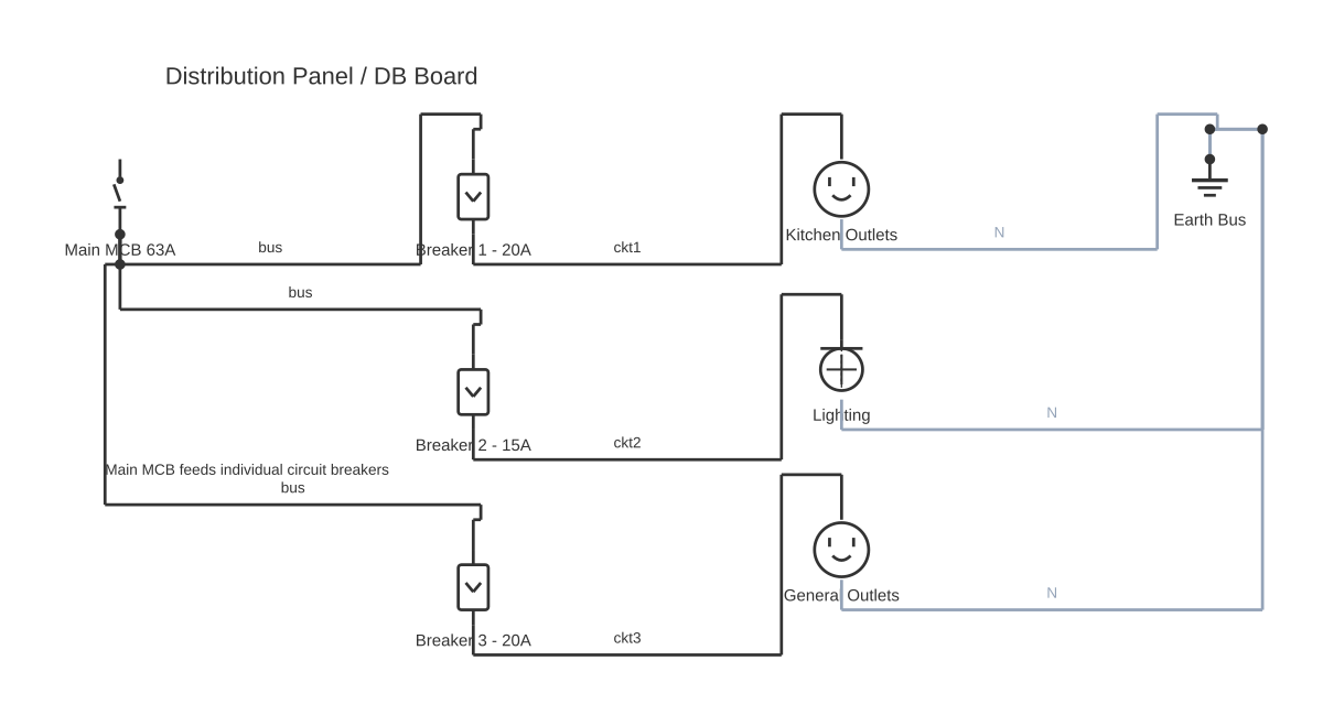
A house wiring diagram is a floor-plan-based drawing that shows every outlet, switch, light fixture, and circuit in a home — annotated with the conductors, breaker assignments, and wire gauges that tie them back to the distribution panel. You need one before applying for an electrical permit, during any renovation, or simply to document what is already installed. This guide explains exactly how to create one from scratch, covering NEC placement rules, GFCI and AFCI requirements, wire gauge notation, home-run arrows, and the panel schedule — including the specific details no other resource covers clearly.
A house wiring diagram serves three distinct purposes, and understanding all three shapes what you put on it. The first purpose is communication: a clearly drawn diagram tells a contractor, inspector, or future owner exactly what circuits exist, where they run, and how they are protected — without opening a single wall. The second purpose is code compliance: in the United States, any new electrical work in a residence requires a permit from the authority having jurisdiction (AHJ), and the permit application requires a wiring diagram that demonstrates compliance with the adopted edition of NFPA 70 (NEC). Most US jurisdictions currently adopt the 2020 or 2023 NEC. The third purpose is a record of the as-built installation: an updated diagram stored with the panel door becomes the authoritative reference for every future owner and electrician.
Before drawing a single symbol, homeowners and contractors need to understand the permit and inspection requirements in their jurisdiction. Pulling a permit is not just a formality — it triggers an inspection by a licensed electrical inspector who verifies that the installation meets code. Work done without a permit cannot legally be sold with a home in most states and may invalidate homeowners' insurance in the event of a fire. In most jurisdictions, a licensed electrician must perform or directly supervise the work; some jurisdictions permit homeowners to do their own wiring for their own primary residence, but the permit requirement still applies. The wiring diagram submitted with the permit application does not need to be professionally drawn, but it must clearly show circuit locations, breaker ratings, and wire gauges.
The NEC establishes specific placement rules for outlets that must be reflected in a code-compliant wiring diagram. NEC Article 210.52 requires that no point on a wall in a habitable room shall be more than 6 feet from an outlet — which in practice means outlets are spaced no more than 12 feet apart along any continuous wall surface. Every wall space 2 feet wide or wider requires an outlet. Countertop circuits in kitchens require outlets within 24 inches of each countertop edge and at each island or peninsula 24 inches by 12 inches or larger. Bathrooms require at least one outlet within 36 inches of the outside edge of each sink basin.
GFCI (ground fault circuit interrupter) protection is required by NEC 210.8 in locations where shock hazard from moisture is elevated: all bathroom outlets, all kitchen countertop outlets within 6 feet of a sink, all garage outlets, all outdoor outlets, all unfinished basement outlets, all crawl space outlets, all boat dock outlets, and any outlet within 6 feet of a laundry sink. On your diagram, GFCI outlets carry a 'GF' label or a specific GFCI symbol. A single GFCI outlet can protect downstream standard outlets on the same circuit if they are connected to the GFCI's LOAD terminals — mark this on your diagram with a note showing the protection extends to listed outlets.
AFCI (arc fault circuit interrupter) protection is required by NEC 210.12 in all 15A and 20A, 120V branch circuits in dwelling units serving bedrooms, living rooms, dining rooms, family rooms, kitchens, laundry areas, hallways, and closets — effectively all habitable rooms and most utility spaces in new construction and in expanded or rewired sections of existing homes. AFCI breakers detect the irregular current signatures of arcing faults (damaged cords, loose connections) before they cause fires. On your diagram, mark AFCI circuits with an 'AF' notation at the breaker symbol in the panel schedule, or use the AFCI outlet symbol at each protected outlet. Combination AFCI/GFCI protection is now available in a single breaker or outlet device.
Residential wire colour codes under NEC are: black = ungrounded hot conductor (the energised conductor that carries current to the load), white or grey = neutral (grounded conductor that carries return current), green or bare copper = equipment grounding conductor (safety ground, carries fault current only), and red = second ungrounded hot conductor in a multi-wire branch circuit or a 240V two-pole circuit. The 14 AWG conductor is standard for 15-amp circuits. The 12 AWG conductor is required for 20-amp circuits. Heavier gauges serve dedicated high-current appliances: 10 AWG for 30-amp circuits (water heater, small AC unit), 8 AWG for 40-amp circuits (electric range), 6 AWG for 50-amp circuits (large range, EV charger). On your wiring diagram, annotate every circuit home-run arrow with the circuit number, breaker amperage, and wire gauge — for example: '#4 / 20A / 12 AWG'.
US residential electrical service uses a split-phase 240V system. The utility transformer centre-tap is the neutral conductor, and the two outer legs (L1 and L2) are each 120V to neutral but 240V to each other. A standard household circuit uses L1 or L2 plus neutral plus ground — 120V, single-phase. A 240V circuit uses both L1 and L2 (plus ground, and sometimes neutral for ranges and dryers that also have 120V components). A two-pole breaker provides 240V supply by connecting to both L1 and L2 bus bars simultaneously. On a wiring diagram, a 240V circuit is annotated with '2P / 240V' and shows a two-conductor plus ground cable (or two-conductor plus neutral plus ground for ranges and dryers).
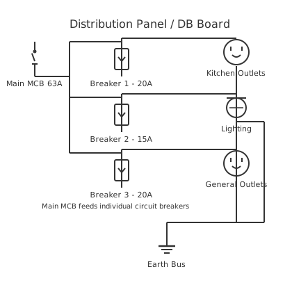
The home-run is the notation that shows where a circuit returns to the distribution panel. On a floor-plan-based house wiring diagram, a home-run is typically shown as an arrow pointing away from the last outlet or fixture in a circuit, labelled with the circuit number (matching the breaker slot in the panel), the breaker amperage, and the wire gauge. When several fixtures share one circuit, they are linked by conductor lines on the floor plan, with a single home-run arrow from the first box to the panel. The panel schedule — a table showing every breaker slot, its circuit number, amperage, connected load, and wire gauge — is the companion document that completes the wiring diagram. Most permit applications require both.
Software makes creating a house wiring diagram far faster than hand drawing, and free options make it accessible to any homeowner. CircuitDiagramMaker.com provides a browser-based residential wiring template pre-loaded with NEC-standard outlet, switch, fixture, GFCI, AFCI, and panel symbols. You can import or trace a floor plan, drag and drop symbols to the correct positions, draw circuit runs, label home-run arrows with breaker data, and export a print-quality PDF suitable for permit applications — all without downloading or installing anything.
How to wire how to make a house wiring diagram
- Obtain or draw a scaled floor plan of the space The standard residential drawing scale is 1/4 inch = 1 foot. Measure each room's length and width and draw the perimeter walls. Mark door and window openings. The floor plan is the base layer over which all electrical symbols will be placed. A digital floor plan (PDF or image) can be imported as a background layer in CircuitDiagramMaker.com.
- Mark all permanent fixtures first: panel location, HVAC, water heater Place the main distribution panel (or load center) symbol first — typically in the garage, utility room, or basement. Note the distance from the utility meter. Mark any subpanel locations. Place HVAC air handler, water heater, and other fixed mechanical equipment symbols, as these define dedicated circuits. These are the anchors around which all other circuits are planned.
- Place outlet symbols per NEC 210.52 spacing rules Work room by room. For each habitable room, place duplex outlet symbols so that no wall point is more than 6 feet from an outlet (12-foot maximum spacing along continuous wall surfaces). Every wall space 2 feet or wider receives an outlet. Mark countertop outlets in kitchens within 24 inches of each countertop edge. Annotate kitchen and bathroom outlets as GFCI (NEC 210.8) using the 'GF' notation on the symbol.
- Add switch symbols at each entry/exit point; use 3-way for two-switch rooms Place single-pole switch symbols (S) at each room entry point beside each door. For rooms with two entry doors, place 3-way switch symbols (S3) at each entry — three-way switching requires a 3-conductor cable (plus ground) between the switches. For rooms with three or more switch points, place 4-way switch symbols (S4) at intermediate positions.
- Add lighting fixtures and note which switch controls each light Place ceiling light, recessed light, ceiling fan, and exhaust fan symbols at their planned positions. Use a dashed control line to indicate which switch controls which fixture — the control line is a drawing convention, not a separate conductor. For the switch leg, the cable runs from the fixture box to the switch box (the hot is switched; the white wire in a 2-conductor cable is re-marked with black tape to indicate it is carrying switched hot).
- Identify GFCI-required circuits and mark AFCI-required circuits Review NEC 210.8 and mark all GFCI symbols: bathrooms, kitchen countertops, garage, outdoors, unfinished basement, within 6 feet of laundry sinks. Review NEC 210.12 and mark all AFCI-protected circuits with 'AF' notation: all habitable rooms and most utility spaces. Combination AFCI/GFCI breakers satisfy both requirements in a single breaker.
- Mark dedicated 20A circuits for kitchen appliances, washer, and dishwasher NEC 210.52(B) requires a minimum of two 20-amp small appliance circuits for kitchen countertop outlets. Add 20A dedicated circuits for: dishwasher, refrigerator, microwave, washer, and any other appliance rated 7.5 amps or higher. Mark these with '20A / 12 AWG' annotations on the home-run arrows.
- Mark 240V circuits for range, dryer, HVAC, and EV charger with correct wire gauge Place 240V outlet symbols (labelled 240V or 30A/50A) for electric range, dryer, HVAC compressor, and any EV charger. Annotate each with the two-pole breaker rating and wire gauge: 10 AWG for 30A (dryer, water heater), 8 AWG for 40A (range), 6 AWG for 50A (large range or EV charger). Note '2-pole' on the breaker symbol in the panel schedule.
- Draw home-run arrows from each circuit to the panel with breaker slot number and amperage From the first outlet or fixture box in each circuit, draw a home-run arrow pointing toward the panel. Label each arrow with the circuit number (e.g. '#4'), breaker amperage (e.g. '20A'), and wire gauge (e.g. '12 AWG'). The circuit number matches the breaker slot number in the panel schedule. Two-pole circuits occupy two consecutive slots.
- Add a legend, symbol key, and title block with address, date, and diagram revision Place a legend in a corner of the drawing defining every symbol used. Include the address, date, your name, and a revision number in the title block. If drawing by hand, add a north arrow. This completed drawing — floor plan with symbols, home-run annotations, and panel schedule — is the standard package submitted with a residential permit application.
Specifications
| Duplex outlet (120V) | Two short vertical lines in a circle. Standard 15A or 20A. 20A type has one T-slot. Designator: WR (weather-resistant) for outdoor. |
|---|---|
| GFCI outlet | Same duplex symbol with 'GF' label or arc-slash mark. Required per NEC 210.8 in bathrooms, kitchens (within 6ft of sink), garages, outdoors, basements. |
| AFCI outlet / breaker | Same duplex symbol with 'AF' label, or AFCI breaker in panel. Required per NEC 210.12 in all habitable rooms and utility areas. |
| 240V outlet (dryer/range) | Circle with three or four slots. Dryer: NEMA 14-30 (4-wire, 30A). Range: NEMA 14-50 (4-wire, 50A). Annotate with '240V' and breaker rating. |
| Single-pole switch | Symbol: S with one curved line. Controls one fixture from one location. Used in rooms with a single entry point. |
| 3-way switch | Symbol: S3. Used in pairs at two entry points for rooms with two doors. Requires 3-conductor + ground cable between switches. |
| 4-way switch | Symbol: S4. Used between two 3-way switches for three or more control points. |
| Dimmer switch | Symbol: S with diagonal arrow. Used for adjustable-brightness lighting circuits. |
| Ceiling light fixture | Circle with X or crosshairs. Mount location on ceiling. Controlled by switch via switched-hot leg. |
| Recessed light | Circle with dot in centre. Can be IC-rated (insulation contact) or non-IC. Mark IC/AT rating for fire safety. |
| Ceiling fan | Circle with F or fan blade symbol. Separate switch legs for fan speed and light if controlled independently. |
| Smoke detector | Circle with S or smoke symbol. NEC 210.12 requires AFCI protection on circuits to smoke alarms in bedrooms. |
| Distribution panel / load center | Rectangle with multiple lines (breaker slots). Labels: main breaker rating, total slots, available slots. Central node for all home-run arrows. |
| Circuit home-run arrow | Arrow pointing from last device in circuit toward panel. Label: circuit number, breaker amperage, wire gauge (e.g. #4 / 20A / 12 AWG). |
| Carbon monoxide detector | Circle with CO label. Required per NEC 210.12 on circuits serving CO alarms in certain jurisdictions. |
| Thermostat | T in a circle. Low-voltage circuit (18-24VAC) run separately from line-voltage circuits. Note: not on a standard branch circuit breaker. |
| Exhaust fan | Circle with E. Bathroom exhaust fans must have GFCI-protected supply if within the bathroom zone. |
| Subpanel | Rectangle labelled SP. Shows feeders from main panel plus local branch circuits. Note feeder gauge and two-pole breaker rating. |
Safety warnings
- Always de-energise and lockout/tagout (LOTO) at the main breaker before working in the panel or on any branch circuit — even with the relevant branch breaker off, the main lugs in the panel remain energised.
- Verify zero voltage with a calibrated non-contact tester and then a multimeter at the specific wire or terminal you intend to handle — a breaker labelled off may not actually be off if the panel has been modified or labelled incorrectly.
- Do not work in the panel without a permit and without complying with the adopted NEC edition — code violations in residential wiring can lead to fires, electrocution, and denial of insurance claims.
- For any uncertainty about panel capacity, grounding, or service entrance work, hire a licensed electrician — service entrance conductors (the wires from the utility meter to the main breaker) are always energised and are the utility's property; work on them requires utility coordination.
Tools needed
- Measuring tape and scaled floor plan (1/4-inch = 1 foot is the standard residential drawing scale; measure every room accurately before placing outlet symbols)
- CircuitDiagramMaker.com (free browser-based editor with pre-loaded residential NEC symbols — GFCI, AFCI, panel, home-run arrows — and PDF export for permit applications)
- Calibrated non-contact voltage tester and multimeter (for verifying de-energised state before accessing any wiring during documentation of an existing installation)
- Panel schedule template (list of all breaker slot numbers, current assignments, amperage ratings, and wire gauges — compare to diagram to confirm circuit labelling is accurate)
- NEC 2020 or 2023 codebook or NEC online subscription (for confirming outlet spacing, GFCI/AFCI requirements, wire sizing, and other code provisions that apply to specific circuits)
Common mistakes
- Spacing outlets more than 12 feet apart along continuous wall surfaces — violates NEC 210.52 and will fail inspection. The rule is no wall point more than 6 feet from an outlet.
- Omitting GFCI notation on kitchen countertop and bathroom outlets — inspectors specifically check GFCI placement; missing protection in these locations is a code violation.
- Forgetting AFCI requirements — the 2020 and 2023 NEC require AFCI protection in virtually all habitable rooms; many homeowners and some contractors are unaware how broadly this now applies.
- Using 14 AWG wire on a 20-amp circuit — 20-amp circuits require 12 AWG. Annotating the wrong gauge on the diagram and then installing accordingly is both a code violation and a fire risk.
- Not annotating home-run arrows with breaker amperage and wire gauge — leaving these unlabelled makes the diagram useless for the permit application and for any future electrician.
- Drawing a 240V appliance circuit as a 2-wire run — dryers and ranges require a 4-wire cable (L1, L2, N, G) per current NEC; older 3-wire hookups are permitted only for grandfathered existing circuits, not new installations.
Troubleshooting
- Permit application rejected — diagram does not show enough detail
- Cause: Inspector needs to see breaker slot assignments, wire gauges, GFCI/AFCI notation, and panel schedule — elements that homeowners often omit from rough sketches Fix: Add the panel schedule table showing every breaker slot, its circuit number, amperage, connected loads, and wire gauge. Add GFCI and AFCI notations at every required location. Label every home-run arrow with circuit number, breaker amperage, and wire gauge. Resubmit.
- Existing outlet does not work after tracing the wiring diagram to its circuit
- Cause: Upstream GFCI outlet on the same circuit has tripped — GFCI protects all downstream outlets on its LOAD terminals Fix: Locate the GFCI outlet that provides protection for this circuit on the diagram. Press the TEST button then the RESET button on the GFCI device. If the GFCI will not reset, there is a ground fault in the circuit — trace each downstream outlet for moisture intrusion or a damaged cord.
- Lights flicker or circuit trips intermittently without obvious overload
- Cause: Loose wire connection at an outlet or junction box, or an AFCI breaker detecting arcing at a damaged insulation point Fix: De-energise and LOTO. Inspect every accessible connection on the circuit for loose terminals, aluminium-to-copper junctions without approved connectors, or damaged insulation. Tighten all screw terminals. For AFCI trips, replace any damaged cords, fix staple-over-cable situations, and check for pinched wiring.
- 240V appliance (dryer, range) is not working but breaker is not tripped
- Cause: One leg of the 240V supply has failed — a two-pole breaker can have one pole trip while the other remains closed, resulting in only 120V reaching the appliance Fix: With the appliance disconnected, use a multimeter to measure voltage between L1 and L2 at the outlet — you should read 240V. Measure L1 to neutral and L2 to neutral — each should read approximately 120V. If one leg reads 0V, the breaker pole has failed or the utility supply has lost one phase. Reset the breaker; if the leg voltage does not return, replace the two-pole breaker.
Frequently asked questions
Do I need a permit to wire my own house?
In the vast majority of US jurisdictions, yes — any new circuit installation, panel replacement, or significant electrical modification requires a permit from your local authority having jurisdiction (AHJ). Some jurisdictions allow homeowners to pull their own permits for work in their primary residence; others require a licensed electrician. Check with your local building department before starting. Work without a permit can void homeowners' insurance and complicate future home sales.
What wire gauge do I use for a 20-amp circuit?
12 AWG copper wire is required for 20-amp, 120V branch circuits under NEC 310.12. Using 14 AWG on a 20-amp breaker is a code violation — the thinner wire can overheat before the breaker trips. For 15-amp circuits, 14 AWG is acceptable. For 30-amp circuits, use 10 AWG. Always match the wire gauge to the breaker rating, not just the connected load.
What is the NEC 6-foot rule for outlet placement?
NEC 210.52(A) states that no point along a wall in a habitable room shall be more than 6 feet from a receptacle outlet, measured horizontally. This means outlets are spaced so that a 6-foot appliance cord can reach an outlet from any point along the wall — in practice, outlets are placed every 12 feet or less. Wall spaces 2 feet wide or wider each require their own outlet.
What is a GFCI outlet and where is it required?
A GFCI (ground fault circuit interrupter) outlet monitors for leakage current between the hot and neutral conductors. If the imbalance exceeds about 5 milliamps — indicating current is flowing through a person to ground — the GFCI trips in milliseconds, preventing electrocution. NEC 210.8 requires GFCI protection in bathrooms, kitchen countertops within 6 feet of sinks, garages, outdoors, unfinished basements, crawl spaces, and within 6 feet of laundry sinks.
What is the difference between a 2-wire and 3-wire circuit?
A 2-wire circuit (technically 2-conductor + ground) carries one hot conductor and one neutral, plus a bare or green ground wire — used for standard 120V circuits. A 3-wire circuit (3-conductor + ground) carries two hot conductors (black and red) and one neutral, plus ground — used for 240V circuits (dryer, range) or multi-wire branch circuits. On a wiring diagram, annotate 3-wire runs as '3W+G' and 2-wire runs as '2W+G'.
What is US split-phase 240V wiring?
North American residential service uses a split-phase system: the utility transformer has a centre-tapped secondary winding, providing two 120V legs (L1 and L2) that are 240V apart. Standard 120V circuits use one leg plus neutral. 240V appliance circuits (range, dryer, HVAC, EV charger) use both L1 and L2. A two-pole breaker in the panel connects to both bus bars simultaneously. Some 240V loads (ranges, dryers) also use neutral for internal 120V components, requiring a 4-wire cable (L1, L2, N, G).
Can I use a floor plan app to draw a house wiring diagram?
General floor plan apps (Cedreo, RoomSketcher, etc.) are not designed for electrical documentation and lack the NEC-compliant symbol libraries, circuit annotation tools, and export formats needed for permit applications. A dedicated electrical diagram tool like CircuitDiagramMaker.com provides all the residential symbols — GFCI, AFCI, panel, home-run arrows — plus PDF export suitable for permit submissions.
What is a home-run in electrical wiring diagrams?
A home-run is the notation showing the point where a circuit returns to (or departs from) the main distribution panel. On a floor-plan wiring diagram, it appears as an arrow pointing away from the first outlet or fixture in a circuit, labelled with the circuit number (breaker slot), amperage, and wire gauge. The home-run arrow is the connection between the floor plan drawing and the panel schedule.