Wiring Diagram Basics: Every Symbol, Rule, and Method You Need

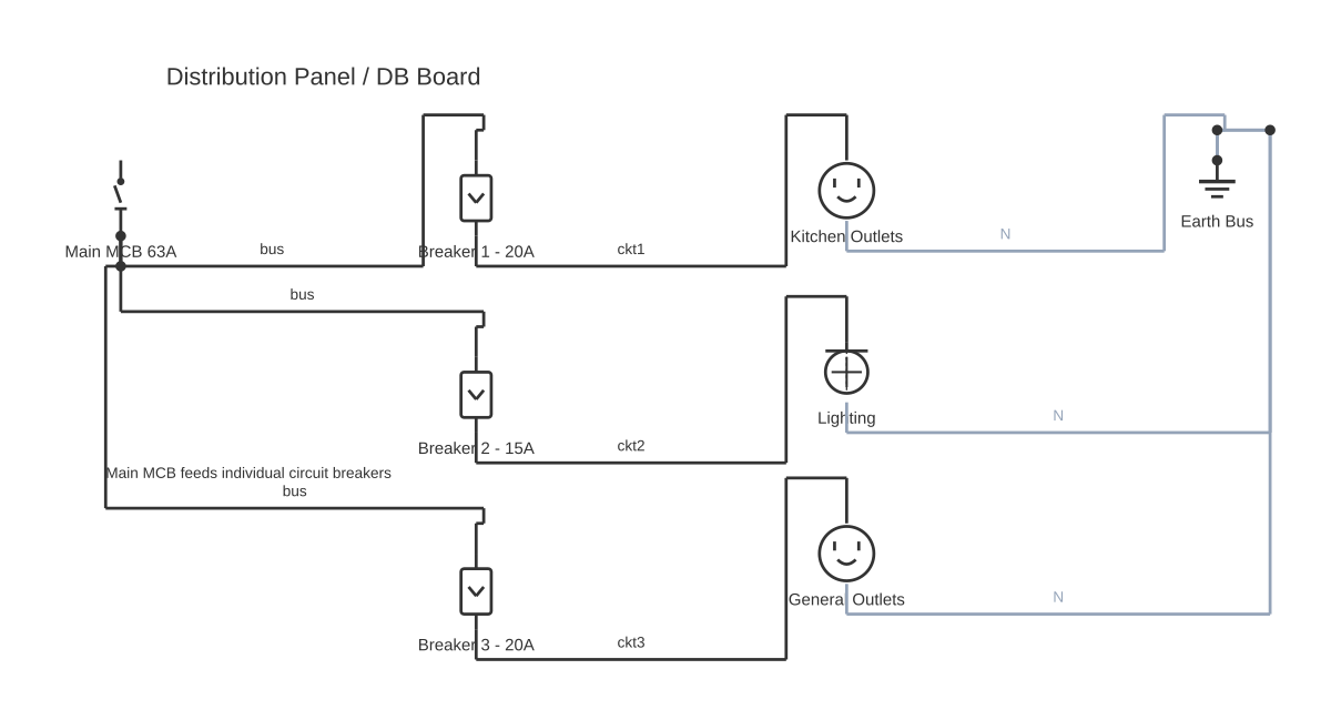
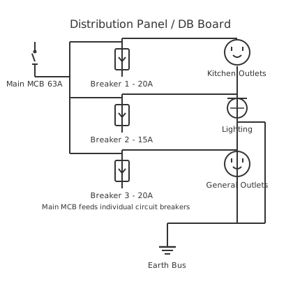
Wiring Diagram Basics: The Complete Beginner's Guide — circuit diagram showing component connectionsMain MCB 63ABreaker 1 - 20ABreaker 2 - 15ABreaker 3 - 20AKitchen OutletsLightingGeneral OutletsEarth BusDistribution Panel / DB BoardMain MCB feeds individual circuit breakers
Wiring Diagram Basics: Every Symbol, Rule, and Method You Need — interactive diagram. Open it in the editor to customise components and wiring.

This is a free printable wiring diagram basics: download the diagram as SVG or open it and print to paper or PDF.
A wiring diagram is a simplified, standardised drawing that shows the electrical connections between components in a system — using agreed symbols instead of pictures of real parts. Understanding the basics lets you read, troubleshoot, and draw diagrams safely, whether you are wiring a home circuit, a motor-control panel, or a custom electronics project. This guide covers every foundational concept in one place: diagram types, symbols, line codes, the neutral condition rule, and a proven 6-step reading method.

A wiring diagram represents every conductor, component, and connection in a circuit using internationally agreed graphic symbols. Unlike a photograph or a pictorial diagram (which shows parts as they actually look), a wiring diagram strips everything back to function: you see where voltage enters, how it flows through switches and protective devices, which loads it energises, and where it returns. That abstraction is exactly what makes wiring diagrams universally useful — an electrician in Johannesburg and a technician in Tokyo can read the same drawing without speaking the same language, provided they both know the symbol set.

Before reading any wiring diagram it helps to know what it is NOT. A wiring diagram is not a schematic, even though the terms are often used loosely as synonyms. A true schematic (also called a circuit diagram) emphasises theoretical electrical relationships and component values — it is the language of electronics design, used by engineers on PCBs. A wiring diagram, by contrast, emphasises physical routing and connection points, making it the language of installation and maintenance. A pictorial diagram goes further and shows realistic images of cables and terminals but provides no functional information. Know which type you are looking at before you start tracing.

There are five recognised categories of electrical drawing, and each serves a different purpose. A schematic diagram shows every component value and connection without regard for physical layout. A ladder diagram (used heavily in industrial and PLC programming) arranges control circuits as horizontal rungs between two vertical power rails, making logic sequences very easy to follow. A block diagram condenses large systems into functional boxes connected by lines, useful for high-level planning. A single-line diagram (SLD) represents three-phase power systems with one line per phase to reduce clutter. A pictorial or wiring diagram shows physical layout and is the most common type for residential and automotive work. Knowing which type you have in front of you determines the reading strategy you apply.

Every wiring diagram has three layers of information: graphic symbols (what the components are), lines (how they connect and what type of conductor is involved), and annotation (labels, tags, and the title block that tell you where you are in the system). The title block, found in the lower-right corner of professional drawings, contains the system name, drawing number, revision letter, date, author, and approver. Always read this block first — a revision-level mismatch between a diagram and a physical panel is one of the most common sources of troubleshooting error.

Line types carry meaning beyond simple connections. A solid, standard-weight line represents a power conductor carrying the main circuit current. A dashed or dotted line represents a control or protective circuit, or — in industrial diagrams produced to DIN/IEC conventions — field wiring that is installed on-site rather than factory-wired. A bold or heavy line indicates the line side (high-current supply side) of a circuit, while thin lines indicate the control side. Understanding these conventions immediately tells you where the dangerous energy lives on the diagram.

Wire colour codes are a critical annotation layer, especially in residential work. The US National Electrical Code (NFPA 70 / NEC) establishes the following standard for 120/240V systems: black = ungrounded hot conductor, white or grey = neutral (grounded conductor), green or bare copper = equipment grounding conductor, and red = second hot conductor in a multi-wire branch circuit or 240V supply. Industrial wiring in North America may follow NEC Article 310 for power and NFPA 79 for machinery wiring, which introduces yellow (ungrounded control), blue (ungrounded DC control), and other variants. IEC systems in Europe and internationally use brown for live, blue for neutral, and green-yellow stripe for protective earth — a combination that often surprises North American technicians encountering imported equipment.

The single most important conceptual rule that beginners miss is the neutral condition rule. All components on a wiring diagram — every switch, every relay contact, every push button — are drawn in their de-energised, rest-state position. A normally open (NO) contact is shown open. A normally closed (NC) contact is shown closed. No coil is energised, no motor is running. This is not an error in the diagram; it is a deliberate convention so that every reader starts from the same baseline. When you energise the system and coil K1 pulls in, you know from the diagram that all contacts labelled K1-NO will close and all contacts labelled K1-NC will open — because you saw their rest position on the drawing. Violating this mental model is the number-one cause of misdiagnosed faults by inexperienced technicians.

Reference designators are short alphanumeric codes assigned to every component on a diagram. Under IEC 81346-1, the addressing system uses three structural levels: = (system/function), + (location/panel), and – (element/component). So –K1 is contactor 1 within the current location, +Panel1–K1 identifies it within a specific panel, and =MotorControl+Panel1–K1 places it within a specific functional system. Wire tags (also called wire numbers or ferrule labels) mark every conductor so that when you are standing in front of a real panel you can match the physical wire to the line on the diagram. Net labels serve a similar purpose in multi-page diagrams: instead of drawing a physical wire across pages, you place the same label on both ends (e.g., +24V or M1-START) to declare that the two points are electrically identical.

Cross-references are the navigation system of multi-page wiring diagrams. When a relay coil on page 3 controls contacts on pages 7 and 12, the coil symbol carries a cross-reference table showing the sheet and row or column coordinate of each contact. A contact symbol on page 7 carries a back-reference to the coil on page 3. Well-drawn diagrams make this automatic; poorly drawn ones omit it entirely, forcing the reader to hunt. Software tools like EPLAN Electric P8 and AutoCAD Electrical generate cross-references automatically.

Creating your own wiring diagram is now accessible to everyone through free browser-based tools. CircuitDiagramMaker.com offers a drag-and-drop interface with both IEC 60617 and ANSI Y32.2/IEEE 315 symbol libraries, auto-snap wire routing, and one-click export to PNG, SVG, or print-ready PDF — no download required. Start from a blank canvas or choose a pre-built template, place your symbols, connect them, add wire tags and annotations, and share a link or export your finished diagram in minutes.

How to wire wiring diagram basics

  1. Read the title block and legend Before tracing a single wire, locate the title block (usually bottom-right). Note the system name, drawing number, revision letter, and date. Then read the legend to confirm every non-standard symbol used in this specific diagram. A mismatch between diagram revision and physical installation explains the majority of 'the diagram is wrong' complaints.
  2. Identify voltage sources and ground references Find every power supply symbol — AC voltage source, DC source, or battery — and note the voltage level, frequency (AC), and polarity (DC). Locate all earth ground and chassis ground symbols. These are your energy entry and reference points; every circuit path starts or ends here.
  3. Locate main protective devices to understand circuit boundaries Find the main fuse, circuit breaker, or isolator. This device defines the boundary of the protected circuit. Any fault downstream of this device is contained within the circuit boundary shown on the diagram. Note its rating (amperage, interrupt capacity) — it also tells you the maximum current the system is designed to carry.
  4. Trace the line (power) side from supply to the first load Follow the bold or heavy conductor from the supply rail through the protective device and any main switching contacts to the first load (motor, heater, lamp). Read left-to-right and top-to-bottom on most North American and European industrial drawings. Identify every component in series on this path.
  5. Follow the control/signal side through every switch and relay coil Trace the thinner control conductors that operate contactors and relays. Note every push button, selector switch, and relay contact in series on each control rung. Remember the neutral condition rule: all contacts are shown in their de-energised state. Build a mental sequence: pressing START closes NO contact, energises coil K1, K1-NO contacts close to maintain the circuit, and so on.
  6. Verify all return paths lead back to neutral or ground, and check cross-references Every complete circuit must have a return path: from the load back to the neutral rail (N or L2), protective earth, or the negative rail on a DC system. Verify each path is unbroken. For multi-page diagrams, use the cross-reference coordinates on coils and contacts to navigate between sheets and confirm the full circuit topology.

Specifications

Wire / conductor lineSolid horizontal or vertical line; represents any electrical conductor. Bold = line-side (high current); thin = control-side.
Junction (node)Filled dot at wire intersection = electrical connection. No dot at crossing = wires pass over with no connection.
Battery (DC source)One long and one short parallel line per cell; multi-cell = alternating long-short pairs. + marks the long (positive) plate.
Voltage source (AC)Circle containing a sine-wave symbol; labelled with voltage and frequency (e.g. 230V 50Hz).
Ground (earth)Three horizontal lines decreasing in length downward (pyramid-down); represents earth reference. Chassis ground uses three angled lines.
FuseRectangle or S-curve in series with the conductor. Designator: F. Labelled with current rating (e.g. F1 / 10A).
Circuit breakerSmall square with a diagonal line through it in series with the conductor. Designator: CB or QF.
SPST switch (NO)Open break in a line with an angled arm pivoting away from one contact. De-energised position per neutral condition rule.
SPDT switchAngled arm pivoting between two fixed contact points. Used for 3-way switching in residential; transfer switching in industrial.
Push button NOOpen contact pair with a horizontal operator line above. Normally open — closes only when button is pressed.
Push button NCClosed contact pair with a horizontal operator line above and a diagonal slash through the contacts. Opens when button is pressed.
Relay coilRectangle labelled with designator K (e.g. K1). When energised, all associated K1-NO contacts close and K1-NC contacts open.
Contactor coil / contactSame rectangle symbol as relay coil but designator M or C. Contacts drawn separately as switch symbols cross-referenced to coil.
MotorCircle with M inside. Represents any rotating electrical machine. Designator: M (e.g. M1). Connected to load terminals of contactor.
TransformerTwo coils facing each other, sometimes with a core line between. Designator: T. Labelled with primary/secondary voltages.
Lamp / indicatorCircle with X or filament symbol inside. Designator: H (indicator) or EL (lamp). Used for status indication on control panels.
Duplex outlet (residential)Two short parallel lines in a circle (ANSI). GFCI variant adds 'GF' label; 240V variant shows three or four slots.
Resistor (ANSI)Zigzag line in series. IEC equivalent is a plain rectangle. Designator: R. Labelled with ohm value (e.g. R1 / 470Ω).
Net label / potential lineNamed flag or arrow attached to a wire. All points with identical labels are electrically connected regardless of physical proximity on the drawing.

Safety warnings

Tools needed

Common mistakes

Troubleshooting

Circuit traces correctly on diagram but load does not energise in the field
Cause: Physical wiring may differ from diagram due to undocumented field modification, or diagram revision is out of date Fix: Verify diagram revision against as-built records. Trace conductor by conductor using wire tags, confirming each terminal matches the diagram annotation.
Wire junction shown on diagram but continuity test shows wires are not connected
Cause: Loose or corroded terminal block connection, or a junction was drawn in error and corrected in the field without updating the diagram Fix: Inspect the physical terminal block or splice at the junction location. Tighten or replace terminals. Update diagram if field change was deliberate.
Relay coil energises but associated contacts do not change state
Cause: Wrong contacts being tested (cross-reference error), or contacts are welded/failed open Fix: Return to the coil symbol on the diagram and follow the cross-reference table to locate the exact page and row of each contact. Test continuity across the correct contact terminals. Replace relay if contacts are welded.
Cannot find a net label on adjacent pages of a multi-page diagram
Cause: Net label naming inconsistency between pages, or diagram was created by multiple authors without a unified naming convention Fix: Search the full document for the label string. Check whether an underscore, hyphen, or capitalisation variant is used on other pages. Raise a drawing correction to standardise labels.

Frequently asked questions

What is the difference between a wiring diagram and a schematic?

A wiring diagram emphasises physical connections, routing, and installation details using agreed symbols. A schematic (circuit diagram) emphasises theoretical electrical relationships and component values without regard for physical layout. Schematics are used for electronic design; wiring diagrams are used for installation and maintenance.

What does a dot (junction) on a wiring diagram mean?

A filled dot at the intersection of two or more wires means those wires are electrically connected — current can flow between them. No dot at a crossing means the wires simply cross over each other with no connection. Some older styles use a bridge arc (hop) to make a non-connection crossing unambiguous.

How do I read wire colour codes on a wiring diagram?

In NEC (North American) systems: black = hot, white/grey = neutral, green/bare = ground, red = second hot. IEC/European systems use brown = live, blue = neutral, green-yellow = protective earth. Industrial control wiring may use yellow (ungrounded AC control) or blue (DC control). The legend or notes section of the diagram usually specifies which colour standard applies.

What are reference designators and wire tags?

A reference designator is a short code (K1, M3, F2) that uniquely identifies each component on the diagram and on the physical equipment. A wire tag (wire number/ferrule label) is a numeric or alphanumeric code printed on a sleeve at each end of a physical conductor, matching the wire ID shown on the diagram. Together they let a technician locate any component or conductor in seconds.

What is the neutral condition rule?

The neutral condition rule states that all components on a wiring diagram — switches, relay contacts, push buttons — are drawn in their de-energised, resting position. Normally open (NO) contacts appear open; normally closed (NC) contacts appear closed. No coil is energised. This baseline allows every reader to apply the same logic when imagining how the circuit behaves when power is applied.

Can I draw a wiring diagram by hand or do I need software?

Hand drawing is perfectly valid for simple residential sketches or quick field notes. For anything more complex — multi-page industrial diagrams, documents for permits, or drawings you will share with contractors — dedicated software is strongly recommended. Free browser-based tools like CircuitDiagramMaker.com give you a full IEC and ANSI symbol library, snap-to-grid routing, and PNG/SVG/PDF export at no cost.

What is a ladder diagram and how does it differ from a wiring diagram?

A ladder diagram arranges a control circuit as horizontal rungs between two vertical power rails (like the sides of a ladder). Each rung represents one logical control statement: a combination of contacts in series/parallel that energises a coil or output. A wiring diagram shows the same circuit but arranged to follow physical conductor routing. Ladder diagrams are the preferred format for PLC programming and motor control documentation.

What is a net label and when should I use one?

A net label (also called a potential line or voltage marker) is a named flag placed on a wire to declare its electrical identity — for example +24V, GND, M1-START, or L1. Any two points carrying the same net label are electrically connected regardless of whether a physical line is drawn between them. Use net labels wherever drawing long wire routes across a diagram would create clutter, especially on multi-sheet drawings.

Related diagrams

Free electrical calculators

Edit this diagram free in the online editor