fan wiring diagram with capacitor
This is a free printable fan wiring diagram with capacitor: download the diagram as SVG or open it and print to paper or PDF.
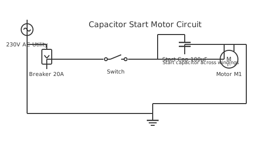
Detailed wiring diagram explanation for fan wiring diagram with capacitor systems and circuit architecture.
How to wire fan wiring diagram with capacitor
- Read the motor nameplate Note the voltage, frequency, full load current, and capacitor rating (μF) from the motor nameplate. These values are non-negotiable — wire the motor exactly to its nameplate specification or it will overheat and fail prematurely.
- Identify motor terminal types Open the motor terminal cover. Most single-phase fan motors have 3 or 4 terminals. A 3-terminal motor (C, M, S) takes supply on C (common). A 4-terminal motor may have speed taps. Photograph the terminal arrangement before removing any wires.
- Install overload protection Install a motor-rated MCB or thermal overload relay in the supply. Set it to the motor's FLC. A fan motor running 10% above nameplate current will have its insulation life halved — protection is not optional.
- Mount the capacitor Mount the capacitor securely away from hot motor surfaces. Capacitor life is strongly temperature-dependent — an electrolytic capacitor running at 10°C above its rated temperature has half the expected service life.
- Wire supply to motor common terminal Connect brown (live) through the overload protection and switch to the motor C (common) terminal. Connect blue (neutral) to the motor's neutral terminal. Connect green/yellow earth to the motor frame earth terminal.
- Connect capacitor Connect capacitor terminal 1 to the motor S (start winding) terminal. Connect capacitor terminal 2 to the motor M (main winding) terminal. Use correctly rated insulated spade terminals — no bare wire connections inside a motor terminal box.
- Verify earth continuity Test earth continuity from the supply earth pin to the motor frame with a multimeter before energising. A motor frame that is not earthed will present a lethal shock hazard if insulation fails.
- Test run and measure current Start the motor and measure running current after 30 seconds. Compare to nameplate FLC. If current is significantly higher than nameplate, the capacitor value may be wrong or the motor has a mechanical fault.
Frequently asked questions
Where does the capacitor connect in a fan wiring diagram?
The capacitor connects between the start winding terminal and the run winding terminal (or common, depending on motor design). It sits in parallel with one winding, not in series with the supply. The supply connects to the motor's common terminal.
What is the difference between a start capacitor and a run capacitor in a fan?
Most domestic fans use a permanent split capacitor (PSC) motor with only a run capacitor that stays in circuit continuously. A start capacitor is used only during starting and disconnected by a centrifugal switch — fans with start capacitors are less common but used in some industrial applications.
How do I wire a fan for speed control with a capacitor?
Speed-controlled fans use a tapped winding motor with multiple common terminals (typically labelled H=high, M=medium, L=low). The capacitor connects the same way regardless of speed selection — the speed is changed by switching which winding tap the supply connects to.
My fan starts slowly and only reaches speed after warming up — why?
This is a classic failing capacitor symptom. As the capacitor degrades, its capacitance drops, reducing the phase shift and starting torque. The motor eventually reaches speed through mechanical momentum once the main winding builds up sufficient current. Replace the capacitor.
Can I use a higher voltage-rated capacitor if the capacitance matches?
Yes. A capacitor rated at 450V AC can replace one rated at 400V AC if the capacitance (μF) is identical. A higher voltage rating simply means a more robust capacitor. Never use a lower voltage rating than the original.
Related diagrams
- 3 wire ceiling fan connection with capacitor
- ceiling fan connection with capacitor
- 6 lead single phase motor wiring diagram with capacitor
- ceiling fan capacitor wiring diagram
- fan capacitor connection diagram
- single phase motor wiring diagram with capacitor