How to Read a Wiring Diagram: A Complete 10-Step Method
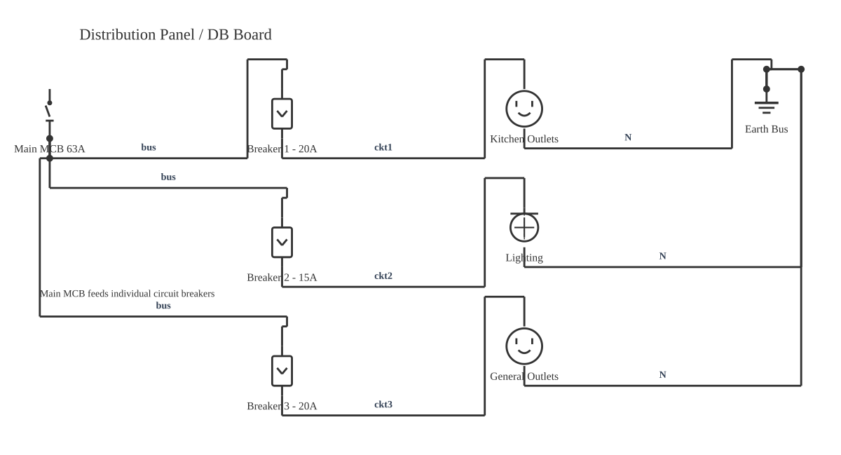
This is a free printable how to read a wiring diagram: download the diagram as SVG or open it and print to paper or PDF.
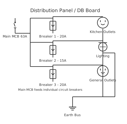
Reading a wiring diagram is a systematic skill, not guesswork — and anyone can master it with the right framework. Once you understand the five core elements (symbols, line types, tags, annotations, and the neutral condition rule), you can decode any diagram from a residential panel to a multi-page industrial machine drawing. This guide walks through a complete 10-step method, explains every critical concept competitors overlook, and shows you how to physically match a diagram to a real panel.
Diagram checks and scope
- Components
- 8
- Wired connections
- 9
- Automated check
- Automated pin, route, source, and topology checks passed; this is not a safety certification.
Why does reading wiring diagrams matter? Because every electrical fault, every installation, and every modification eventually comes back to paper — or screen. A technician who can read a diagram confidently can trace a fault in minutes that would otherwise require hours of probing random terminals. An installer who understands diagrams places every wire correctly the first time. And a safety professional who can read a diagram knows exactly which conductors are energised before anyone opens a panel door.
Two competing symbol standards are in active use worldwide, and you will encounter both. ANSI Y32.2 / IEEE 315 is the North American standard, still dominant in US industrial and commercial work. IEC 60617 is the international standard used throughout Europe, Asia, and on most modern imported equipment. The most common visible difference is the resistor: ANSI draws it as a zigzag line; IEC draws it as a plain rectangle. Other differences accumulate: IEC switch contacts use a different diagonal convention, relay coils use a rectangle (same as ANSI), and ground symbols have slight variations. Spending 20 minutes with a side-by-side symbol table before approaching an unfamiliar diagram pays dividends throughout any troubleshooting session. Industrial reference designation uses IEC 81346-1 — the standard that assigns structured addresses like =MotorDrive+Panel1–K3 to every device.
The neutral condition rule is the rule that most beginners violate, and it is the source of more confused troubleshooting than any other single misunderstanding. Every switch, contact, and push button on a wiring diagram is shown in its de-energised rest position — as if the entire system has been sitting unpowered. A normally open (NO) contact is shown with a gap. A normally closed (NC) contact is shown touching. No coil is energised. This is not a mistake in the diagram; it is a universal convention that allows you to reason about the circuit's behaviour from first principles. When you press the START button, you close an NO contact and energise coil K1. Because you know K1's contacts are shown in their rest (open) position, you know that when K1 energises, all K1-NO contacts close and all K1-NC contacts open — anywhere in the diagram, on any page.
Reading direction in wiring diagrams follows a consistent convention: left to right for the horizontal axis (power flows left to right in most European and North American industrial drawings) and top to bottom for sequential logic. In a ladder diagram, each rung is read left to right as a complete logical expression — a series of conditions (contacts) that, when all satisfied, produce an output (coil or load). In a schematic-style wiring diagram, power typically enters from the top-left (L1) and the return path (L2, N, or neutral) runs along the right or bottom. Understanding this direction convention tells you immediately which end of any conductor is the supply side and which is the load side.
Line types encode information beyond simple conductors. A standard solid line carries the main circuit current — power wiring, load conductors. A dashed or dotted line signals a control or protective circuit, or, in DIN-compliant industrial diagrams, field wiring that is installed on-site rather than wired in the factory. The distinction between factory wiring and field wiring matters enormously during commissioning: field-wired connections are the installer's responsibility; factory-wired connections should already be complete on a new machine. Bold conductors represent the high-current line side (L1 to load); thin conductors represent the low-current control side (typically 24VDC or 120VAC control voltage).
Wire tags and device tags are the bridge between the diagram and the physical installation. A wire tag is a number or alphanumeric code printed on a heat-shrink sleeve or clip-on ferrule at both ends of every conductor. On the diagram, the same code appears beside the conductor line. When you are standing in a panel looking for wire 1042, you scan ferrules until you find it — then you trace it on the diagram to see exactly where it goes and what circuit it belongs to. Device tags follow IEC 81346-1 addressing: = identifies the functional system, + identifies the location (panel, cabinet, field), and – identifies the individual element. A device labelled =Conveyor+Cabinet1–K3 is contactor 3 in Cabinet 1 of the Conveyor system. This structured addressing means large multi-cabinet machines with hundreds of components can be navigated systematically.
Net labels (potential lines or voltage markers) allow a wiring diagram to represent connections between widely separated points without drawing a physical wire across many pages. A conductor labelled +24V at one end of the diagram is electrically identical to every other conductor labelled +24V — the label is the connection. Voltage markers like L1, L2, L3, N, GND, +24VDC, and 0VDC appear throughout industrial diagrams to show power-rail membership. In multi-page drawings, net labels are the primary cross-sheet connection method — a conductor leaving page 4 as M1-RUN arrives on page 11 carrying the same label.
Cross-references are the index system for multi-page diagrams. When relay coil K1 appears on sheet 3 and controls contacts on sheets 7 and 12, the coil symbol carries a cross-reference table below it listing sheet number and row or column coordinate for every associated contact. Each contact on sheets 7 and 12 carries a back-reference pointing to the coil on sheet 3. In software-generated diagrams (EPLAN Electric P8, AutoCAD Electrical), cross-references are built automatically and update when the diagram changes. In hand-drawn or older diagrams, they may be absent or incomplete — forcing the reader to hunt. Building the habit of checking cross-references before concluding a circuit trace is complete is one of the most valuable practices a technician can develop.
Identifying the control section versus the load section is another foundational reading skill. The load section carries the main circuit current and connects directly to motors, heaters, lighting circuits, and other energy-consuming equipment. The control section carries low-power signals that operate relay and contactor coils, pilot lights, and PLC inputs. In a motor-starter diagram, the load section shows the three-phase supply running through contactor M1 contacts to motor terminals — thick lines, high current. The control section shows a start/stop push-button circuit that energises the M1 coil — thin lines, 24VDC or 120VAC. Always identify which section you are in before drawing conclusions about voltage levels and current ratings.
Double-level terminal blocks and electrical interlocking are two advanced topics that rarely appear in beginner resources but come up constantly in real industrial work. A double-level terminal block is a two-storey terminal that allows a conductor from the field (bottom level) to connect to an internal panel conductor (top level) without an additional wire link — it saves panel space and simplifies wiring. On a diagram, these appear as stacked rectangle symbols with internal dividing lines. Electrical interlocking uses NC contacts from one contactor wired in series with the coil of a second contactor, preventing both from energising simultaneously. You will see this in any forward/reverse motor starter: the forward contactor's NC contact is in series with the reverse coil, and vice versa. Recognising this pattern on a diagram immediately tells you the circuit's safety intent. Use CircuitDiagramMaker.com's free drag-and-drop editor to build your own diagrams with all IEC and ANSI symbols pre-loaded — annotate with wire tags, add net labels, and export a print-ready PDF to share with your team.
How to wire how to read a wiring diagram
- Gather documentation: title block, legend, BOM, and manufacturer datasheets Start by collecting every supporting document. Read the title block for system name, drawing number, and revision. Read the legend to understand every non-standard symbol. Locate the Bill of Materials (BOM) for component model numbers, and pull relevant manufacturer datasheets for motors, PLCs, and control devices. A diagram without its supporting documentation is only half the picture.
- Identify the power supply type, voltage level, and phase count Find the power supply symbol or incoming terminals. Determine: AC or DC? Single-phase, split-phase 240V, or three-phase? What voltage level (24VDC control, 120VAC, 230VAC, 480VAC)? Note this prominently — it governs meter range settings and PPE requirements before any physical work begins.
- Locate the main disconnect or breaker — your starting point The main protective device (MCB, MCCB, fuse-switch) is the boundary of the circuit shown in this diagram. Everything downstream is protected by this device. Its amperage rating tells you the maximum normal current. Trace from here in both directions: downstream toward loads, and upstream toward the supply.
- Identify the line side vs the control side Separate the high-current load conductors (bold lines running from supply through contactor power contacts to motor terminals) from the low-current control conductors (thin lines running through push buttons, selector switches, and relay contacts to coil and PLC input terminals). This mental separation prevents errors: a test reading on the control side uses very different instrument settings than the load side.
- Find all loads — these are your circuit endpoints Locate every motor (circle with M), lamp, solenoid, heater, or other energy-consuming component. These are the destinations of every circuit path. Working backwards from a load through the control logic that switches it is often faster than tracing forwards from the supply, especially on complex diagrams.
- Trace each control circuit from the power rail through contacts to the coil or load Starting from the control power rail, follow each rung left to right. List every contact in series: their designators, their rest-state positions (NO/NC per neutral condition rule), and which coil or device they ultimately switch. Build a word description: 'When START (NO) is pressed and STOP (NC) is closed and K1-NC is closed, coil K2 energises.'
- Note every node, junction, and potential line along each path Mark all filled-dot junctions (connections) and confirm all crossings without dots are non-connections. Note every net label and potential line — verify that the same label appears on all conductors that should be electrically tied. A missing junction dot or a net label typo is enough to cause an intermittent or permanent fault.
- Check cross-references if the circuit continues on another page When you reach a coil, look below it for the cross-reference table showing every associated contact location. Navigate to each sheet and row coordinate. When you reach a contact, look for its back-reference to the coil. Confirm the full energisation path is logically consistent across all pages.
- Verify interlocks and safety circuits Identify every NC contact wired in series with a contactor coil — these are hardware interlocks. Confirm that the forward and reverse contactors (in a reversing starter), or the Star and Delta contactors (in a star-delta starter), are properly interlocked. Safety circuits (emergency stop, guard monitoring) should appear as NC contacts in a series chain — any break de-energises the output.
- Compare the diagram to the physical panel: match wire tags to physical labels With the system safely de-energised and locked out, open the panel and identify wire ferrule labels. Match each ferrule to its corresponding wire number on the diagram. Follow the conductor from terminal to terminal, confirming each connection matches the diagram. This final step validates the diagram against reality and reveals any undocumented field modifications.
Specifications
| Battery | Long + short parallel lines (multi-cell = alternating pairs). Designator: GB. Polarity: + at long plate. |
|---|---|
| Resistor ANSI/IEC | ANSI: zigzag line. IEC: plain rectangle. Designator: R. Value label in ohms (Ω, kΩ, MΩ). |
| Capacitor non-polar | Two parallel vertical lines with gap. Designator: C. Value in farads (nF, µF). |
| Inductor / coil | Series of arcs or loops. Designator: L. Value in henries (µH, mH). |
| Ground (earth) | Three horizontal lines decreasing downward (pyramid). Chassis ground: three angled lines. Protective earth per IEC: circle with cross. |
| SPST switch (NO) | Open break in line with angled arm. Designator: S or SW. Shown de-energised per neutral condition rule. |
| SPDT switch | Pivot arm between two contacts. Used for 3-way residential switching and transfer switching. |
| Relay coil | Rectangle labelled K (K1, K2…). When energised, all same-designator NO contacts close; NC contacts open. |
| Contactor coil / contacts | Rectangle labelled M or C. Power contacts drawn separately. Contacts cross-referenced to coil page/row. |
| Fuse | Rectangle in series OR S-curve in series. Designator: F. Rated in amperes (e.g. F1/10A). |
| Circuit breaker | Square with diagonal through it. Designator: CB or QF. Rated in amps and interrupting kA. |
| Motor | Circle with M inside. Designator: M (M1, M2…). Connected at load terminals of contactor or VFD output. |
| Transformer | Two facing coils ± core lines. Designator: T. Labelled primary/secondary voltages and VA rating. |
| Diode | Triangle pointing to bar. Current flows in direction of triangle. Designator: D. |
| LED | Diode symbol with two outward arrows. Used for pilot lights and status indicators. Designator: D or H. |
| Push button NO | Open contacts with horizontal operator line above. Closes only when pressed. Designator: SB or PB. |
| Push button NC | Closed contacts with operator line and diagonal slash. Opens when pressed. Designator: SB or PB. |
| Junction / node | Filled dot = electrical connection. No dot at crossing = wires cross without connecting. |
| Terminal block | Rectangle with internal horizontal dividing lines. Designator: X or XT. Double-level variant has two tiers. |
Safety warnings
- De-energise and apply lockout/tagout (LOTO) before physically working on any circuit identified in a wiring diagram — a diagram tells you what is connected, not what is safe.
- After locking out, verify zero voltage with a calibrated meter at every conductor you intend to touch, even if the diagram shows it as switched off.
- Industrial diagrams often include multiple power sources and control voltages — confirm all sources are isolated before opening an enclosure.
- Arc flash: use appropriate PPE (arc-rated clothing, face shield) rated to the incident energy level at the panel — the diagram shows circuit topology but does not specify arc flash boundaries.
Tools needed
- Calibrated multimeter or non-contact voltage tester (for verifying de-energised state and tracing circuit continuity in the field)
- Printed or on-screen wiring diagram at the correct revision level (use CircuitDiagramMaker.com to create, annotate, and export diagrams)
- Highlighter set (for marking traced paths on printed diagrams — use one colour per circuit traced to avoid confusion)
- Wire tag / ferrule reference list (for matching physical labels to diagram annotations when working in a panel)
- Manufacturer datasheets for motors, relays, and PLCs (for confirming pin designations and coil voltage ratings against the diagram)
Common mistakes
- Assuming a wire crossing without a dot is connected — always check for the filled junction dot before concluding two wires share a node.
- Ignoring the neutral condition rule and reading contact symbols as their current operating state rather than their de-energised rest position.
- Failing to follow cross-references when tracing a relay coil's contacts across pages, leading to incomplete fault analysis.
- Mixing up ANSI and IEC symbols on diagrams that combine both standards — always check the legend for which standard governs.
- Not verifying diagram revision against as-built records before using the diagram for troubleshooting or modification.
Troubleshooting
- Load does not energise despite control circuit tracing correctly on diagram
- Cause: Physical wiring differs from diagram — field modification not reflected in current revision, or wrong diagram revision in use Fix: Confirm diagram revision matches the as-built record. Trace physical conductors using wire tags, checking each terminal matches the diagram. Document any discrepancy and update the drawing.
- Relay coil energises but associated load contacts do not switch
- Cause: Welded or failed relay contacts, or technician is testing the wrong contact (cross-reference error) Fix: Return to the coil on the diagram and consult the cross-reference table for the exact page and row of each contact. Test continuity across those specific terminals. Replace relay if contacts are failed welded or open.
- Interlock does not prevent second contactor from energising
- Cause: NC interlock contact has failed welded (fused closed), bypassing the interlock function Fix: Test the NC contact while the associated coil is de-energised — it should read closed. Then energise the coil — it should open. If it remains closed while energised, the contact is welded and the relay or contactor must be replaced immediately.
- Net label appears on multiple pages but conductors at those points measure different voltages
- Cause: Net label naming error — two different circuit nodes were given identical labels, or one instance of the label was mistyped Fix: Trace each net label instance back to its power source. If two instances connect to different voltage sources, a naming error exists in the diagram. Correct the label in the drawing and physically verify the wiring matches the intended topology.
- Cannot match wire tag in panel to any annotation on the diagram
- Cause: Wiring was added or modified in the field without updating the diagram, or wire tag label was applied incorrectly during installation Fix: Trace the unidentified wire to both its termination points using a continuity tracer. Identify the components it connects, then locate those components on the diagram to infer the wire's function. Update the diagram with the missing wire annotation.
Frequently asked questions
What is the neutral condition rule in wiring diagrams?
The neutral condition rule states that every switch, relay contact, push button, and other switching device is drawn in its de-energised resting position. Normally open contacts appear open; normally closed contacts appear closed. No coil is energised in the diagram. This allows every reader to analyse the circuit from the same known baseline.
What does a dot between two wires mean on a wiring diagram?
A filled dot at a wire intersection means the wires are electrically connected at that point — current can flow between them. No dot at a crossing means the wires simply pass over each other without connecting. Always look for the dot before assuming a connection exists.
How do I read cross-references in a multi-page wiring diagram?
A cross-reference appears as a small table below a relay coil listing the sheet number and row/column coordinate of every associated contact in the diagram. When you find a contact, its back-reference points back to the coil sheet. Navigate between sheets using these coordinates to trace the complete circuit without losing your place.
What is a wire tag and how do I find it on the diagram?
A wire tag is a number or alphanumeric code that appears on the diagram beside a conductor line, and on a physical heat-shrink ferrule at each end of the real conductor. To find a wire tag on the diagram, scan the label annotations beside conductor lines. In the panel, scan the ferrule labels on each wire end until the tag matches.
What is the difference between the line side and the control side?
The line side (or load side) carries the main circuit current — typically three-phase or single-phase supply voltage running through contactor power contacts to motors and other heavy loads. The control side carries low-power signals (often 24VDC or 120VAC) that operate relay coils, PLC inputs, and pilot lights. Line side uses bold conductor symbols; control side uses thin conductor symbols.
How do wire colour codes work in industrial wiring diagrams?
In NEC-governed North American installations: black = ungrounded hot, white/grey = neutral, green/bare = equipment ground, red = second hot or DC positive. In IEC/European installations: brown = live, blue = neutral, green-yellow = protective earth. NFPA 79 (industrial machinery) adds yellow = ungrounded AC control, blue = DC control. The diagram's notes section or legend specifies which standard applies.
Why do some diagrams use dashed lines instead of solid lines?
Dashed lines indicate either control or protective conductors (lower current, switch-level signals) or, in DIN/IEC-style drawings, field wiring that is installed on-site by the commissioning team rather than pre-wired in the factory. Solid bold lines indicate main power conductors. The specific meaning of dashed lines is always defined in the diagram legend.
How do I read an electrical interlock in a wiring diagram?
An electrical interlock appears as a normally closed (NC) contact from one contactor wired in series with the coil of a second contactor. If contactor A is energised and its NC contact opens, it physically prevents contactor B from energising. In a forward/reverse starter, both contactors interlock each other this way. Look for NC contacts labelled with a different contactor's designator in any coil energisation rung.
Sources and verification
Review status: Not independently reviewed. Automated topology checks confirm stored terminals and routes, not the correctness of manufacturer pin assignments, ratings, regional codes, or installation decisions. Verify those claims against the current primary documentation before use.
- IEC 61082-1:2014 — Rules for electrotechnical documents — International Electrotechnical Commission. Supports: General diagram, drawing, table, and reference-designation presentation conventions. Checked 2026-07-15.
Full written guides
Related diagrams
- how to make a house wiring diagram
- wire a switch to a light
- wiring a switch to an outlet
- wiring led lights to a 12v battery diagram
- 4 to 2 encoder circuit diagram
- 5 wire trailer wiring to 7 pin diagram