JVC Car Stereo Wiring Diagram: ISO Harness Connections Explained
This is a free printable jvc car stereo wiring diagram: download the diagram as SVG or open it and print to paper or PDF.
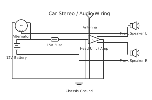
A JVC car stereo wiring diagram shows how to connect a JVC aftermarket head unit to a vehicle using the standard ISO 10487 harness, identifying the colour-coded wires for power, ground, speakers, and accessories common to JVC units.
JVC aftermarket car stereos connect to vehicle wiring through a wiring harness that follows the ISO 10487 automotive audio connector standard, supplemented by JVC's own published colour-coding convention for the pigtail wires bundled with their units. The standard ISO 10487 connector divides into two 8-pin blocks: ISO-A (power and control) and ISO-B (speaker outputs).
This page describes the general colour conventions documented by JVC for their aftermarket head unit range. Because JVC releases many different models and the specific colour assignments can vary between model families, always cross-reference with the installation manual supplied with the specific unit before making any connection. If the original manual is unavailable, download the correct version from JVC's official support site using the unit's model number, which is printed on the front panel or on a label on the chassis.
General JVC pigtail colour conventions (verify against your specific model's manual):
Yellow: constant 12 V DC (memory/battery supply). Always live from the battery. Must be individually fused, typically 10–15 A. Connects to the head unit's memory circuit.
Red: ignition-switched 12 V (ACC/accessory supply). Live only when the ignition switch is in the ON or ACC position. Controls whether the unit powers on or off.
Black: chassis ground. Must connect to a clean, low-resistance vehicle earth point.
Blue or blue/white striped: amplifier remote/aerial motor turn-on. Outputs 12 V when the unit is powered on to trigger an external amplifier or powered aerial.
Speaker outputs (ISO-B, standard JVC colour convention): Front left positive: white; Front left negative: white/black stripe. Front right positive: grey; Front right negative: grey/black stripe. Rear left positive: green; Rear left negative: green/black stripe. Rear right positive: violet (purple); Rear right negative: violet/black stripe.
Important: these colour codes represent the widely published JVC convention but are not guaranteed to match every JVC model without verification. Wire colour conventions within the same brand can change across product generations. The striped wire is always the negative of the pair.
Vehicle-specific harness adapters are available for most vehicles and allow plug-and-play connection without cutting factory wiring.
How to wire jvc car stereo wiring diagram
- Obtain the installation manual for your specific JVC model Locate the model number on the unit's front face or chassis label (format typically begins with KD-, KW-, or similar). Download or locate the correct installation manual before touching any wires. The manual contains the definitive wiring diagram for that model. Do not rely solely on generic colour conventions, including those on this page, as they can differ between product lines.
- Disconnect the negative battery terminal Remove the negative (black) battery cable from the battery terminal before any wiring work. Wait 60 seconds. This prevents short circuits and protects vehicle electronics. On vehicles with start-stop systems or advanced battery management, consult the vehicle's service documentation before disconnecting the battery, as some require a re-initialisation procedure after reconnection.
- Obtain and prepare the vehicle harness adapter Source the correct vehicle harness adapter for the vehicle's make, model, and year. If the vehicle has steering wheel audio controls, also obtain a compatible SWC (steering wheel control) interface module. The harness adapter has a vehicle-side plug that matches the factory connector and an ISO-A and ISO-B socket on the aftermarket side.
- Connect the JVC pigtail to the harness adapter or vehicle wiring Match each JVC pigtail wire to its counterpart in the harness adapter or, where direct connection is necessary, to the vehicle wiring. Use the model's installation manual as the definitive reference. Connect: yellow to permanent 12 V; red to ignition-switched 12 V; black to chassis earth; blue/white to amplifier remote (if applicable). Join wires using insulated crimp connectors or soldered and heat-shrunk joints. Never use insulation tape alone on a vehicle installation — vibration causes tape to fail.
- Connect the speaker outputs Connect each speaker pair from the ISO-B harness adapter to the vehicle's speaker wiring: front left (white/white-black), front right (grey/grey-black), rear left (green/green-black), rear right (violet/violet-black). The striped wire in each pair is negative. Ensure no speaker output wire contacts a chassis earth point.
- Connect optional accessories Connect the GPS antenna to the GPS antenna port if the unit has navigation. Connect the external microphone for hands-free and position it at the A-pillar. Connect a rear camera to the camera input if fitted. Connect the parking brake wire to the handbrake signal wire or to chassis ground (verify local road traffic laws regarding head unit video use while moving).
- Test before fitting in the dash and reconnect the battery Reconnect the negative battery terminal. Turn the ignition to ACC and verify the unit powers on, audio plays from all four speakers, and all connected functions (Bluetooth, navigation, camera) operate. Test the ignition-off condition: the unit should power off. Only slide the unit into the dash pocket after confirming correct operation, to avoid repeated dash disassembly.
Specifications
| Yellow wire function | Constant 12V DC (memory/battery); permanently live; fused 10–15 A |
|---|---|
| Red wire function | Ignition-switched 12V DC (ACC); powers unit on/off with ignition |
| Black wire function | Chassis ground (0 V reference); must connect to clean, low-resistance earth point |
| Blue/white wire function | Amplifier remote output; 12V when unit is on; used for external amp turn-on |
| Speaker output colour convention (JVC general) | FL+: white; FL−: white/black. FR+: grey; FR−: grey/black. RL+: green; RL−: green/black. RR+: violet; RR−: violet/black. Verify against specific model manual. |
| ISO connector standard | ISO 10487 (ISO-A: power/control 8-pin; ISO-B: speaker 8-pin) |
| Head unit form factor (typical) | Single-DIN 180 mm × 50 mm or Double-DIN 180 mm × 100 mm (ISO 7736) |
| Reference document | JVC model-specific installation manual (obtain from JVC official support using unit model number) |
Safety warnings
- Always disconnect the vehicle's negative battery terminal before beginning any wiring work. Failure to do so risks short circuits that can blow fuses, damage vehicle control modules, or cause fire.
- The constant 12V (yellow) wire must be fused as close to the battery positive terminal as practicable. This wire runs outside the protection of the vehicle's factory fuse box and is a fire risk if it chafes against body metalwork without a fuse.
- Never touch or disturb the yellow or yellow-striped wiring associated with the vehicle's airbag system (SRS). This wiring can trigger airbag deployment, causing serious injury.
- Do not connect any speaker output wire to chassis ground. JVC's internal amplifier (and all standard aftermarket head unit amplifiers) uses a bridged output that will be damaged or destroyed if a speaker output is grounded.
Tools needed
- Trim removal tools (plastic, non-marring)
- Multimeter (DC voltage range, for identifying ignition-switched and permanent 12V supplies)
- Wire stripper
- Crimping tool (matched to insulated butt connectors)
- Heat gun (for heat-shrink tubing)
- Screwdrivers (flat and Phillips/Pozidriv)
- Test light (12V, for quick supply identification)
Common mistakes
- Connecting the red wire (switched 12V) to a permanent supply: the unit stays on after the ignition is off and drains the battery.
- Connecting the yellow wire (constant 12V) to a switched supply: the unit loses clock and settings every time the ignition is turned off.
- Grounding a speaker output wire to chassis: destroys the internal amplifier output stage, often immediately and without any other warning.
- Not obtaining the correct vehicle-specific harness adapter: using a generic adapter or incorrectly matched adapter may result in incorrect speaker or power wiring, or loss of vehicle-specific features (canbus interface, factory amplifier bypass, etc.).
- Ignoring the factory amplifier in factory-amplified vehicles: the result is very low audio output or distortion, as the head unit's speaker-level output is not designed to drive an unamplified passive speaker through the factory amp's signal path.
Troubleshooting
- Head unit has no audio from speakers after installation
- Cause: Vehicle has a factory amplifier receiving no or incorrect signal; or speaker wires not correctly connected via harness adapter Fix: Determine whether the vehicle has a factory amplifier by checking a vehicle wiring resource or the factory service manual. If a factory amp is present, obtain an amplifier retention adapter or bypass module. If no factory amp, use a multimeter in continuity mode to verify the head unit speaker outputs match the speaker wiring through the harness adapter.
- Head unit powers off immediately after the ignition is turned off, losing presets
- Cause: Yellow (constant 12V) wire is connected to a switched supply Fix: With ignition off, measure voltage on the yellow wire. If it reads 0 V, the wire is incorrectly connected to a switched source. Re-route to a permanent 12V supply (via an inline fuse).
- Audio has a buzzing or whining noise that changes with engine speed
- Cause: Poor chassis earth connection for the head unit; alternator noise coupling into the audio circuit Fix: Check and improve the black (ground) wire connection. Run a dedicated earth wire from the head unit chassis to a clean, bare-metal bolt on the vehicle body. If the problem persists, fit a ground loop isolator on the speaker outputs or an EMI filter on the power supply leads.
Frequently asked questions
Why should I use a vehicle harness adapter instead of cutting and splicing wires directly?
A harness adapter preserves the vehicle's original wiring, allowing you to restore the factory stereo at any point without lasting damage to the wiring loom. Cutting factory wiring can reduce vehicle resale value and, if done incorrectly, create wiring faults that are difficult to trace later. Adapters are inexpensive and are the industry-standard approach for aftermarket installation.
What happens if I connect the red and yellow wires to the wrong supplies?
If the yellow (constant 12V) wire connects to the ignition-switched supply, the unit loses all stored settings (clock, presets, equaliser) every time the ignition is turned off. If the red (switched 12V) wire connects to the permanent supply, the unit stays on after the ignition is off and will drain the battery. Both errors are common and easy to diagnose with a multimeter.
What does the blue or blue/white wire on a JVC head unit do?
The blue or blue/white wire is the amplifier remote (also called power antenna or remote out). It outputs approximately 12 V when the head unit is on. Connect it to the remote input of an aftermarket amplifier to turn the amplifier on and off with the head unit. Also used to trigger a motorised aerial motor, raising the antenna when the radio is on.
My JVC head unit has no orange or orange/white wire. How do I connect the illumination?
Not all JVC models include an illumination wire. On those that do, an orange or orange/white striped wire connects to the vehicle's lighting circuit, dimming the display when the headlights are on. If your unit lacks this wire and the display is too bright at night, check the head unit's settings menu — most JVC units allow manual display brightness adjustment independent of an illumination input.
Can I use a JVC head unit in a vehicle that originally had a factory-amplified system?
Yes, but you need to account for the factory amplifier. Many modern vehicles route head unit audio output through a factory DSP or amplifier before it reaches the speakers. Connecting a standard harness adapter in these vehicles gives very low volume. You need either a factory amplifier bypass adapter (retaining the factory amp) or an aftermarket amplifier connected to the head unit's RCA pre-amplifier outputs.
Full written guides
Related diagrams
- 10.1 android car stereo wiring diagram
- car stereo power supply diagram
- car stereo wiring diagram
- car stereo wiring harness diagram
- chinese android car stereo wiring diagram
- 1 4 stereo jack wiring diagram