Outlet Wiring Diagram: Hot, Neutral and Ground Terminal Connections
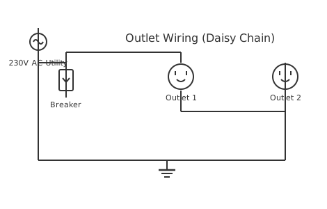
This is a free printable outlet wiring diagram: download the diagram as SVG or open it and print to paper or PDF.
An outlet wiring diagram shows how to connect the hot, neutral and ground conductors from branch circuit wiring to the correct terminals of a standard duplex receptacle, ensuring safe and code-compliant installation.
Diagram checks and scope
- Components
- 5
- Wired connections
- 5
- Automated check
- Automated pin, route, source, and topology checks passed; this is not a safety certification.
A standard 15 A or 20 A 120 V duplex outlet — formally called a receptacle — has three conductor connections. The hot terminal, identified by a brass-coloured screw, receives the black or red ungrounded conductor from the branch circuit. The neutral terminal, identified by a silver-coloured screw, receives the white grounded conductor. The ground terminal, identified by a green screw or a green hexagonal nut, receives the bare copper or green insulated equipment grounding conductor. This three-wire arrangement ensures that under normal operation current flows only between hot and neutral, while the ground conductor carries no current but provides a fault return path if insulation fails inside an appliance. The branch circuit originates at the panel where the circuit breaker connects the black conductor to the hot bus and the white conductor to the neutral bus bar. The ground bus connects to the neutral bus only at the main service panel — this single-point bond prevents neutral current from flowing through the ground path under normal conditions. Installing multiple outlets on one circuit follows daisy-chain or home-run topology. In daisy-chain wiring, the cable runs from the panel to the first outlet, then continues from that outlet to the next, and so on. Each outlet has its hot, neutral and ground pigtailed or wired through from one cable to the next. The limitation of daisy-chain wiring is that an open neutral at an early outlet leaves all subsequent outlets without a neutral return path. Home-run wiring runs a separate cable from the panel to each outlet, which is more material-intensive but eliminates inter-outlet dependencies and simplifies circuit tracing. GFCI protection is mandatory in bathrooms, kitchens within 1.8 m of sinks, garages, outdoors, crawl spaces, and unfinished basements per NEC 210.8. A GFCI outlet can protect downstream outlets on the same circuit by connecting the load terminals of the GFCI to the line terminals of subsequent standard outlets, enabling one GFCI device to protect an entire circuit at fraction of the cost of individual GFCI outlets at each location.
Half-Switched Outlet Wiring: Breaking the Brass Tab for Independent Control
A half-switched outlet (also called a half-hot or split receptacle) is a standard duplex receptacle wired so that one socket is controlled by a wall switch and the other remains always-hot. This configuration is common in living rooms and bedrooms that have no ceiling light fixture — the NEC allows a switched outlet to satisfy the code requirement for a switched lighting outlet in a habitable room.
The key physical step is removing the break-off tab on the hot (brass) side of the receptacle. This small brass fin bridges the two brass screws, making both sockets share the same hot supply. Grip it with needle-nose pliers or diagonal cutters and work it back and forth until it snaps off. Remove only the brass tab — leave the silver (neutral) tab intact. Removing the neutral tab would separate the neutral for each socket, which is only appropriate if the two halves are on completely separate circuits with separate neutrals, each protected by a shared-neutral (multi-wire branch circuit) with a two-pole breaker.
With the brass tab removed, the two brass screws are now electrically independent. One screw receives the always-hot black wire (permanent supply); the other receives the switched-hot wire from the wall switch. Convention places the switched socket at the top, so the switched-hot connects to the upper brass screw — but either half can be switched depending on which brass screw the switched wire lands on. The 3-conductor cable required for this circuit is 14/3 or 12/3 NM-B: black (always-hot), white (neutral), red (switched-hot), and bare ground. A standard 14/2 cable cannot support a half-switched outlet because there is only one hot conductor.
How to wire outlet wiring diagram
- Turn off and verify de-energised Switch off the circuit breaker and verify zero volts on all three conductors at the outlet box with a non-contact tester. Tag the breaker with a lockout label.
- Strip and prepare conductors Strip 19 mm of insulation from black, white and bare conductors. Form J-hooks on the black and white wires for screw terminals. Straighten the bare ground wire for the ground screw or pigtail.
- Connect ground first Attach the bare copper or green ground conductor to the green ground screw on the outlet. If multiple cables enter the box, pigtail all ground wires together and run one pigtail to the outlet ground screw.
- Connect neutral (white) to silver screw Hook the white conductor clockwise around the silver-coloured neutral screw. Tighten to approximately 1.1 Nm. Verify no bare copper extends beyond the screw head.
- Connect hot (black) to brass screw Hook the black conductor clockwise around the brass-coloured hot screw. Tighten to the same torque. Fold conductors into the box and mount the outlet. Restore power and verify with a circuit tester.
Specifications
| Standard outlet rating | 15 A at 125 V AC (NEMA 5-15R) or 20 A (NEMA 5-20R) |
|---|---|
| Hot terminal | Brass screw — black conductor |
| Neutral terminal | Silver screw — white conductor |
| GFCI trip threshold | 5 mA ground fault current within 25 ms |
Safety warnings
- Always verify zero voltage on all three conductors with a non-contact tester before touching the outlet box — the neutral can remain energised if the circuit has a downstream fault.
- Never connect the neutral and ground conductors to the same terminal at an outlet — this creates a neutral-ground fault that bypasses GFCI protection and causes nuisance tripping.
- Use a circuit tester after installation to verify hot, neutral and ground polarity — reversed hot and neutral causes shock hazard from appliance chassis to ground faults.
Tools needed
- Non-contact voltage tester for confirming circuit de-energisation before work
- Outlet circuit tester with indicator lights for polarity and ground verification
- Insulated wire strippers rated for 300 V minimum
- Torque screwdriver calibrated to 1.1 Nm for receptacle terminal screws
Common mistakes
- Connecting the hot conductor to the neutral (silver) terminal, reversing polarity and making the appliance chassis live.
- Using the push-in (backstab) connections on the outlet instead of screw terminals, which have higher resistance and loosen with thermal cycling.
- Failing to pigtail the ground wire when multiple cables enter a box, leaving ground continuity dependent on the outlet being installed.
- Removing the silver (neutral) tab instead of, or in addition to, the brass (hot) tab — this creates a floating neutral on one socket unless a separate neutral is wired and a two-pole breaker is installed.
- Using 14/2 cable and trying to wire a half-switched outlet by connecting both the always-hot and the switch leg to the same cable — this does not provide an always-hot socket; both sockets will be switched.
- Connecting the switched-hot wire to a silver (neutral) screw instead of a brass (hot) screw, which places a hot conductor on the neutral terminal and creates a shock hazard.
Troubleshooting
- Outlet has power but nothing works
- Cause: Outlet is GFCI-protected and the upstream GFCI has tripped Fix: Locate the upstream GFCI outlet on the same circuit and press the reset button. If it will not reset, a ground fault in the circuit must be identified and corrected before resetting.
- Outlet circuit tester shows open ground
- Cause: Ground conductor not connected or broken between outlet and panel Fix: De-energise the circuit. Check ground screw connection at the outlet. Trace ground continuity from outlet to panel with a multimeter. Replace wiring or install GFCI protection per NEC exception if ground cannot be restored.
- Outlet sparks when plugging in
- Cause: Loose hot or neutral terminal connection causing arcing Fix: De-energise, remove outlet, and inspect all terminations. Re-torque all screws. If arcing has caused discolouration, replace the outlet. Check for worn backstab connections and switch to screw terminals.
- Both sockets of the split outlet are always on even after removing the brass tab
- Cause: Both the always-hot and switched-hot wires are connected to the same brass screw, or the brass tab was not fully removed and a small piece is still bridging the two screws. Fix: Inspect the brass-screw side of the receptacle with a flashlight. Confirm the tab is fully snapped off with no metal bridge remaining. Verify the always-hot wire and the switched-hot wire are on separate brass screws — one on the upper screw, one on the lower screw.
Frequently asked questions
What is the difference between the hot and neutral slots in an outlet?
The smaller slot on the right side of a standard US duplex outlet is hot — connected to the brass screw and the black circuit wire. The larger slot on the left is neutral — connected to the silver screw and the white wire. The U-shaped slot at the bottom is ground. The size difference is a polarisation safety feature that ensures appliances connect hot to the switched side of their internal circuit.
What causes an outlet to fail the circuit tester?
Common failures include open ground (ground wire not connected or broken), open neutral (neutral wire not connected or broken), open hot (hot wire not connected or broken), hot-neutral reversed, and hot-ground reversed. Each combination produces a unique indicator pattern on a standard outlet tester. The most dangerous condition is hot-ground reversed, which places line voltage on the ground conductor of the entire circuit.
How does a GFCI outlet protect downstream outlets?
The GFCI outlet compares current on the hot and neutral conductors using a differential current transformer. A difference of 5 mA or more indicates ground-fault leakage and triggers the GFCI to interrupt both hot and neutral within 25 ms. When downstream outlets are wired to the GFCI load terminals, the GFCI monitors the entire downstream current loop, providing the same 5 mA trip protection to all connected devices.
Can I replace a two-prong outlet with a three-prong outlet without a ground wire?
NEC 406.4(D)(2) allows replacing an ungrounded two-prong outlet with a GFCI outlet or a GFCI-protected three-prong outlet if no ground wire is available. The GFCI outlet must be labelled "No Equipment Ground." The GFCI protection still provides personnel protection against ground faults even without an equipment ground, though it does not provide equipment grounding for devices that require it.
How much wire should I strip for an outlet terminal?
Strip approximately 19 mm of insulation — about the length of the bare conductor visible on outlet terminal strip diagrams. This length provides sufficient conductor engagement in the screw clamp without excess bare wire that could contact adjacent terminals or the box. For screw terminals, form a J-hook clockwise around the screw shank so tightening the screw draws the conductor inward.
Which tab do I remove to make a half-switched outlet?
Remove only the brass tab on the hot side — the small fin connecting the two brass (hot) screws. Leave the silver tab on the neutral side completely intact. Removing the neutral tab separates the neutral between the two sockets, which requires a two-pole circuit breaker and 14/3 cable with a full separate neutral for each half, making the wiring significantly more complex.
What cable do I need for a half-switched outlet?
You need 14/3 NM-B (or 12/3 on a 20A circuit) with four conductors: black (always-hot), white (neutral), red (switched-hot from the wall switch), and bare copper ground. Standard 14/2 cable provides only one hot conductor and cannot supply an always-on socket and a switched socket simultaneously.
Sources and verification
Review status: Not independently reviewed. Automated topology checks confirm stored terminals and routes, not the correctness of manufacturer pin assignments, ratings, regional codes, or installation decisions. Verify those claims against the current primary documentation before use.
- IEC 61082-1:2014 — Rules for electrotechnical documents — International Electrotechnical Commission. Supports: General diagram, drawing, table, and reference-designation presentation conventions. Checked 2026-07-15.
Related diagrams
- 3 prong dryer outlet wiring diagram
- 4 prong dryer outlet wiring diagram
- 3 prong outlet wiring diagram
- 3 wire outlet diagram
- 4 prong outlet wiring diagram
- 4 wire outlet diagram