Western Plow Wiring Diagram: Isolation Module, Harness Topology and Connection Principles
This is a free printable western plow wiring diagram: download the diagram as SVG or open it and print to paper or PDF.
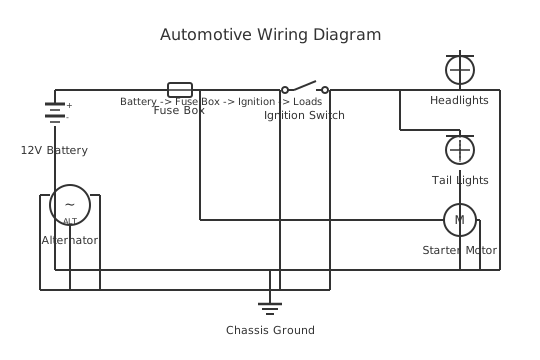
A Western snow plow wiring diagram shows how the vehicle harness, isolation module, and plow-side control harness interconnect to operate the lift, angle, and light functions.
Western Products manufactures snow plows and related equipment for light- and medium-duty trucks. Their electrical interface system uses a modular wiring approach that separates the vehicle's factory wiring from the plow's hydraulic and lighting circuits using an isolation module — a relay and diode assembly that prevents feedback between plow functions and the vehicle's own body control module (BCM) or lighting circuits.
This reference describes the general topology and wiring principles of typical Western plow electrical systems. Exact harness configurations, connector types, and wiring colours differ between plow models (Unimount, Ultramount), vehicle applications, and model years. The authoritative wiring diagram for any specific plow-and-vehicle combination is the installation instruction sheet published by Western Products and available through their dealer network or the manufacturer's website. This content is illustrative and general; it does not substitute for OEM documentation.
A Western plow electrical system typically comprises three interconnecting subsystems. First, the vehicle-side harness connects to the truck's battery, existing lighting circuits (turn signals, running lights, brake), and the isolation module. Second, the isolation module (also called the underhood module) contains relays that control the plow's hydraulic pump motor and solenoids, and diodes that allow the plow's turn and marker lights to operate without backfeeding the vehicle's lighting bus. Third, the plow-side harness connects the isolation module to the plow's headlights, solenoid block, and pump motor.
The control hand-held or cab-mounted joystick controller sends low-current signals to the isolation module's control inputs. The module's relays then switch the high-current circuits for the pump motor and solenoid valves. The plow's hydraulic system typically uses three functions — lift (up/down), angle left, and angle right — each controlled by a solenoid valve on the hydraulic manifold.
Proper grounding is critical in plow electrical systems. A dedicated ground cable from the plow frame to the vehicle chassis is required — relying on the hitch or mount hardware as the ground path introduces resistance that causes lighting faults and solenoid misbehaviour.
How to wire western plow wiring diagram
- Obtain the correct OEM wiring diagram and harness kit Identify the plow model, the vehicle year/make/model/engine, and any existing trailer wiring or aftermarket lighting that may affect the installation. Cross-reference these details with the Western Products application guide to select the correct vehicle-side harness kit and plow-side harness. Download or obtain the printed installation diagram before beginning work — do not attempt to trace existing wiring without the diagram.
- Disconnect the vehicle battery Disconnect the vehicle battery negative terminal before beginning any wiring work. Modern trucks have active BCM circuits and sensitive electronic modules — working with the battery connected risks damaging the BCM, triggering airbag circuits, or corrupting stored module data.
- Mount the isolation module in the engine compartment The isolation module is typically mounted in the engine compartment on a bracket near the battery or fuse box. Route the module away from heat sources (exhaust manifold, turbo plumbing) and areas where it could be hit by road debris. Secure the mounting bracket firmly — the module will vibrate during vehicle and plow operation.
- Connect the battery supply cable and main fuse Connect the module's main power cable to the battery positive terminal via the integrated or separately mounted high-current fuse (often a MEGA or ANL type fuse rated for the pump motor circuit). Keep this cable as short as practical. Route it away from moving parts and heat sources. Connect the module's main ground wire to the battery negative or a known-good chassis ground point.
- Connect the vehicle-side lighting harness Connect the vehicle-side harness to the existing truck headlight and turn signal circuits per the installation diagram. On modern trucks this typically involves a relay-interposer or plug-in adapter at the vehicle headlight connectors rather than direct wiring cuts — consult the vehicle-specific installation sheet for the correct approach. Never cut factory harness connectors without the OEM instructions confirming this is the correct method.
- Route and connect the plow-side harness Route the plow-side harness from the isolation module to the front of the vehicle, exiting through a suitable grommet at the front bumper area. Secure the harness with clips and ties at regular intervals. Leave a service loop at the plow connection point — enough slack that the plow can be attached and detached without straining the harness. Connect the weather-sealed multi-pin connector at the plow mount.
- Install and test the plow ground cable Route a dedicated heavy ground cable (sized per the OEM specification — typically 6 AWG or larger) from a secure, clean bare-metal point on the plow A-frame or frame to a clean chassis ground point on the vehicle. Clean both connection points to bare metal before fitting the ring terminals. A poorly grounded plow will show lighting and solenoid problems that appear as complex faults but resolve immediately with a good ground.
Specifications
| Typical pump motor supply voltage | 12 V DC (North American trucks); verify vehicle system voltage |
|---|---|
| Typical pump motor starting current | 100–300 A surge (varies by plow model and hydraulic load) |
| Main fuse type and location | MEGA or ANL fuse within 500 mm of battery positive terminal; amperage per OEM spec |
| Dedicated ground cable minimum size | 6 AWG (3.3 mm²) minimum; OEM specification may require larger for high-capacity plows |
| Multi-pin connector type (typical vehicle-to-plow) | Weather-sealed multi-pin automotive connector; pin count and gender per plow model |
| OEM documentation source | Western Products official website / dealer network — vehicle and plow model specific |
| Isolation module function | Diode isolation of plow lighting from vehicle BCM circuits; relay switching of pump motor and solenoids |
| Note on this diagram | This content is generic/illustrative. Always use the OEM-published wiring diagram for the specific plow model, harness kit number, and vehicle year/make/model. |
Safety warnings
- Disconnect the vehicle battery negative terminal before working on any plow wiring. Modern truck electronics — including BCMs, airbag modules, and ABS modules — can be damaged by voltage transients or shorts during wiring work performed with the battery connected.
- Never exceed the OEM-specified fuse ratings for the pump motor supply circuit. Snow plow hydraulic motors draw high surge current on startup. Using an oversized fuse to prevent tripping removes the cable protection — a short circuit in a heavy pump motor cable with an oversized fuse will melt wiring and cause a vehicle fire.
- Ensure the plow's dedicated ground cable is correctly installed and makes bare-metal contact at both ends. Poor grounding is the single most common cause of erratic plow lighting and solenoid operation. A high-resistance ground path under pump motor load drops voltage across the ground cable, raising the apparent chassis voltage and causing lighting anomalies.
- Before operating the plow on public roads, verify that all plow lights function correctly — both plow-mounted headlights, amber marker lights, and turn signal integration. In most jurisdictions, the vehicle must have functioning headlights, turn signals, and marker lights even with the plow attached. Check local regulations for any additional lighting requirements for snow removal equipment.
- Hydraulic fluid is flammable and under pressure. After any hydraulic work, check all fittings and lines for leaks before operating the plow. Do not work under a raised plow that is supported only by hydraulic pressure — lower the plow to the ground or support it mechanically before performing any maintenance under or near the plow blade.
Tools needed
- OEM installation diagram (specific to plow model, harness kit, and vehicle — essential)
- Digital multimeter (DC voltage, continuity, resistance)
- Clamp meter (for verifying pump motor current and checking for voltage drop)
- Wire stripper and crimping tool for 6–14 AWG wiring
- Insulated ring terminal crimper (for ground and power cable ring terminals)
- Socket and wrench set (for mounting brackets and battery terminals)
- Electrical contact cleaner and dielectric grease (for multi-pin connector maintenance)
Common mistakes
- Using a generic or non-vehicle-specific harness diagram — harness connector pinouts and relay configurations vary by vehicle BCM type and model year, making a wrong-year diagram worse than useless for diagnosis.
- Skipping the dedicated ground cable or using the mount hardware as the ground return — the mount bolts have painted surfaces and small contact areas that corrode quickly and produce high resistance, causing lighting and solenoid faults that appear random but resolve immediately when a dedicated ground is installed.
- Using a too-small or unrated connector at the vehicle-to-plow junction — the multi-pin connector at the mount point is exposed to water, ice, salt, and mechanical stress every time the plow is attached or detached. Use only weather-sealed connectors rated for automotive use and keep them clean and lubricated with dielectric grease.
- Not securing the plow harness with clips at regular intervals — an unsecured harness chafes against the vehicle frame, suspension components, or exhaust during plow operation and road vibration, eventually cutting through the insulation and creating short circuits.
- Testing only with the plow stationary — some electrical faults (particularly grounding and connector issues) only appear under load when the pump motor is running. Always test all plow functions — full lift, full drop, left angle, right angle — for several complete cycles before signing off on an installation.
Troubleshooting
- Plow does not raise or respond to controller — no pump operation
- Cause: Main power fuse blown; battery supply not reaching isolation module; controller signal not reaching module; or module main power relay not closing Fix: Check the main battery supply fuse first. Measure voltage at the isolation module's main power input terminal with the ignition on. If voltage is present, measure at the module's pump motor output terminal when the raise function is commanded — if voltage appears at the input but not the output, the module relay has failed. If no signal from the controller reaches the module, trace the controller cable for continuity.
- Plow lights are dim or flicker during pump operation
- Cause: Excessive voltage drop in the plow ground circuit — the ground resistance causes the plow frame voltage to rise during pump current draw, which appears as a voltage reduction across the lights Fix: Measure voltage between the plow frame and the vehicle chassis with the pump running. More than 0.3 V indicates a poor ground connection. Inspect the dedicated ground cable at both ends for corrosion, looseness, or bare-metal contact. Clean connections, apply contact compound, and retest. Replace the ground cable if it is undersized for the pump motor current.
- Vehicle turn signals flash at incorrect rate (too fast or too slow) with plow connected
- Cause: Plow turn indicator lamps are creating a load mismatch on the vehicle's electronic turn signal flasher or BCM-controlled lighting output; isolation module diode path may be faulty Fix: Verify that the isolation module diodes are functioning correctly by checking whether the vehicle turn signals work normally without the plow connected. If so, the diode in the module feeding the plow turn lights has failed, allowing plow lamp current to backfeed into the vehicle circuit. Replace the isolation module or its diode assembly per the OEM procedure.
Frequently asked questions
Why does a Western plow use an isolation module instead of wiring directly?
Modern trucks have sensitive body control modules (BCMs) that monitor lighting circuits for open and short conditions. Connecting plow lights and solenoids directly to vehicle wiring can trigger fault codes and BCM-controlled load-shedding that disables the lighting circuit. The isolation module's diodes and relays electrically isolate the plow circuits from the vehicle's BCM-monitored wiring, preventing false faults.
Where can I find the correct wiring diagram for my Western plow and vehicle?
The authoritative source is the installation instruction document published by Western Products for your specific plow model, harness kit number, and vehicle application. Western Products makes installation documents available through their dealer network and on their official website. Harness kit selection depends on the plow model (Unimount, Ultramount, etc.) and the specific truck year, make, and model.
What is the purpose of the plow's dedicated ground cable?
Plow electrical systems carry substantial current through the pump motor circuit — often 100–200 A during hydraulic operation. This current must return to the vehicle battery through a low-resistance ground path. A dedicated heavy ground cable directly from the plow frame to the vehicle chassis ensures a low-resistance return path. Relying on the mount hardware creates a resistive joint that causes voltage drop, lighting dimming, and solenoid misbehaviour.
Why does my plow only raise but not angle, or vice versa?
Each hydraulic function (lift, angle left, angle right) is controlled by a dedicated solenoid valve on the hydraulic manifold. A function that is completely inoperative in one direction typically indicates a failed solenoid coil (open circuit), a missing or blown solenoid fuse, or a wiring fault between the isolation module relay output and the solenoid connector. A function that works slowly in both directions suggests low fluid level or hydraulic pump pressure issues rather than electrical faults.
Is it safe to plow with only one plow headlight working?
Operating with a non-functional plow headlight is both a safety hazard and a legal issue in most jurisdictions — the plow headlights replace the vehicle's front lights when raised into position in many installations, and a non-working plow light leaves the vehicle without proper forward lighting. Diagnose and repair the fault before operating the plow on public roads.
Related diagrams
- western plow wiring harness
- western snow plow wiring diagram
- boss plow solenoid wiring diagram
- boss plow wiring diagram
- boss plow wiring harness
- fisher plow wiring diagram