Western Plow Wiring Harness: Understanding Snow Plow Electrical Harness Circuits
This is a free printable western plow wiring harness: download the diagram as SVG or open it and print to paper or PDF.
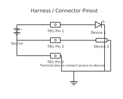
A western-style plow wiring harness connects the vehicle battery, headlamp isolation relays, solenoid valve coils, and controller into a weatherproof circuit built to survive below-freezing conditions.
This page is a generic, illustrative reference for the type of electrical harness architecture used on truck-mounted hydraulic snow ploughs. It does not represent any specific manufacturer's proprietary wiring diagram, pinout, or connector specification. Always consult the manufacturer's official wiring diagram and service manual for your specific plow and vehicle combination before performing any electrical work.
A hydraulic snow plow wiring harness typically divides into three functional sub-harnesses.
The vehicle-side harness connects the truck's battery to the plow control system. A heavy main power cable (typically 2 AWG or 4 AWG, 12 V positive) runs from the battery positive terminal, through a high-current inline fuse (commonly 200 A to 300 A — protection must be as close to the battery as possible, within 450 mm per good wiring practice), to a connector at the front of the vehicle. A matching heavy negative (ground) cable runs from the same battery negative terminal to a chassis ground point near the front bumper. Relying solely on the vehicle's body ground for plow return current is a common source of intermittent faults — a dedicated negative cable to the plow pump motor is best practice.
The plow-side harness connects the pump motor, solenoid valve coils, and plow headlamps to the vehicle-side connectors. The pump motor typically draws 80 A to 200 A during full hydraulic lift, which is why heavy cable gauges and a properly rated solenoid contactor are essential. Solenoid valve coils controlling lift, angle-left, angle-right, and float function draw 1 A to 3 A each at 12 V — these are handled by smaller-gauge wiring through the controller relay outputs.
The headlamp harness isolates the plow headlamps from the vehicle's headlamp circuit using relays, preserving vehicle lighting circuit fuse ratings and preventing backfeed between plow and vehicle lamps.
Connectors throughout the harness must be weatherproof, rated for outdoor and submersion exposure (typically sealed multi-pin connectors with IP67 or higher rating). Dielectric grease applied to all terminals at installation significantly reduces corrosion from road salt and water ingress.
How to wire western plow wiring harness
- Gather documentation before starting Obtain the wiring diagram specific to your plow model and your vehicle year, make, and model. Plow harnesses are often vehicle-specific. Review the installation manual completely before touching any wire. Note which harnesses are included in the kit and which may need to be purchased separately for your vehicle.
- Disconnect the vehicle battery Disconnect the battery negative (−) terminal first, then the positive (+) terminal. Secure both cables away from the battery posts. This prevents shorts and accidental starting during installation. On vehicles with active systems (keyless entry, alarm), note that disconnecting the battery may reset some settings.
- Install the main power fuse holder near the battery Route the main positive cable from the battery positive terminal, through the fuse holder (positioned within 450 mm of the battery), and toward the front of the vehicle. Use a grommet wherever the cable passes through any sheet metal to prevent chafing of the insulation. Secure the cable at regular intervals (every 300 mm to 500 mm) with appropriate cable clips.
- Connect the vehicle-side ground cable Run a heavy-gauge negative cable from the battery negative terminal to a clean, paint-free metal point near the front bumper or mounting bracket. Remove paint or corrosion from the mounting point with a wire brush and apply a direct metal-to-metal contact. Coat the exposed metal around the terminal with electrical corrosion inhibitor after connection.
- Install the headlamp isolation relay and harness Route the headlamp harness to the vehicle's headlamp plugs. The isolation relays intercept the existing headlamp wiring. Follow the harness-specific instruction to identify the vehicle's low-beam and high-beam wires — do not guess colour codes as they vary by vehicle. Use a test light or multimeter to confirm circuit function before reconnecting.
- Connect the vehicle-to-plow connector Mate the vehicle-side harness connector to the plow-side harness connector. These connectors are typically keyed to prevent incorrect mating. Apply dielectric grease to all multi-pin connector cavities before mating to displace moisture and prevent corrosion from road salt exposure.
- Reconnect battery and test all functions Reconnect battery positive then negative. With the plow attached, operate each function from the controller: lift, lower (float), angle left, angle right. Verify each solenoid valve responds correctly. Check plow headlamps on low and high beam. Measure pump motor current with a clamp meter during lift — high current (significantly above rated) indicates a hydraulic or mechanical restriction; low current indicates a wiring or solenoid fault.
Specifications
| Typical main supply cable gauge | 2 AWG or 4 AWG (confirm to specific harness specification) |
|---|---|
| Maximum distance: battery positive to inline fuse | 450 mm (good wiring practice) |
| Typical main fuse rating | 200 A – 300 A (confirm to specific harness specification) |
| Solenoid valve coil operating voltage | 12 V DC |
| Solenoid valve coil current draw (typical) | 1 A – 3 A per coil at 12 V |
| Connector environmental rating | IP67 minimum (weatherproof, intermittent submersion) |
| Headlamp isolation relay contact rating | 40 A (automotive standard relay) |
Safety warnings
- Always disconnect the vehicle battery before working on any part of the plow electrical harness. A short circuit in a heavy-gauge cable connected to the battery can ignite the cable insulation and cause a vehicle fire within seconds.
- The inline fuse on the main positive cable must be installed within 450 mm of the battery positive terminal. This is the only overcurrent protection for the cable between the battery and the fuse — an unfused section can carry full battery short-circuit current (typically 400 A to 1000 A) for as long as it takes the cable to melt or ignite.
- Do not substitute fuse ratings — never fit a higher-rated fuse than specified to cure a blowing fuse. Investigate and repair the cause of the overcurrent. A fuse that blows is detecting a fault; replacing it with a higher-rated fuse removes that protection.
- Plow electrical systems operate in severe environments: road salt, water submersion, impacts, and extreme temperatures. Inspect all connectors, grommets, and cable clips at the start of every snow season. A deteriorated connector or chafed cable that worked at the end of last season may fail completely in the first storm of the next season.
Tools needed
- Digital multimeter (DC voltage, resistance, and continuity)
- Current clamp meter (for measuring pump motor current during operation)
- Wire stripper and heavy-gauge cable cutter (for 2 AWG – 4 AWG cable)
- Hydraulic crimp tool and ring terminals (correct size for cable gauge and stud)
- Insulated screwdrivers and socket set
- Dielectric grease applicator
- Test light (12 V, for quick circuit identification)
- Drill and step bit (for cable routing holes through bodywork if required)
Common mistakes
- Installing the main fuse too far from the battery: every millimetre of cable between the battery and the fuse is unprotected. A common mistake is routing the cable all the way to the firewall before the fuse — if the cable chafes anywhere along that run, there is no protection.
- Relying on vehicle body panels as the primary return path for pump motor current: body panel resistance and paint at bolt joints creates voltage drop that causes slow or failed plow operation and intermittent faults that are difficult to diagnose. Run a dedicated negative cable.
- Using connectors not rated for weatherproof outdoor use: a standard unsealed connector will corrode and fail after one season of road-salt exposure. Use only sealed, IP67-rated connectors with dielectric grease.
- Not securing cables away from steering, suspension, and exhaust components: a cable that contacts a hot exhaust component or gets pulled by suspension movement will fail at the worst possible time. Inspect all cable runs for clearance before final tightening.
- Mixing plow headlamp power into the vehicle headlamp circuit without isolation relays: the combined lamp current exceeds the vehicle's headlamp fuse rating, blowing the fuse and leaving the vehicle without functioning headlamps on a public road at night.
Troubleshooting
- Pump motor does not run when lift is commanded
- Cause: Main fuse blown, high-resistance or open ground connection, solenoid contactor coil not energised, or main positive connection corroded Fix: Check the main inline fuse first — visually inspect and test with a multimeter. Measure battery voltage at the plow-side connector with lift commanded — if below 10 V under load, the positive cable or battery connection has high resistance. Check all heavy-cable connections at battery, fuse, and connector for corrosion. If voltage is present, verify the solenoid contactor is closing by listening for its click when lift is commanded.
- Plow operates but vehicle headlamps do not work correctly with plow attached
- Cause: Headlamp isolation relay failed or not connected, incorrect relay wiring, or vehicle headlamp circuit override not triggered Fix: Check the isolation relay operation: with headlamps on and plow connected, the relay should switch the headlamp circuit from the vehicle lamps to the plow lamps. Verify relay coil receives 12 V when headlamps are activated. Test relay by substitution. Verify the harness connects to the correct vehicle headlamp wires — use a multimeter to confirm rather than relying on wire colour alone.
- Plow angles left or right but will not lift
- Cause: Lift solenoid valve coil failed, lift circuit relay open, or hydraulic pump fluid issue (not an electrical fault) Fix: Measure 12 V at the lift solenoid valve coil connector when lift is commanded. If voltage is present but no movement, the coil or valve itself has failed — test coil resistance (open-circuit or shorted). If no voltage, trace the control circuit from the controller output through the relay to the solenoid. Confirm hydraulic fluid level before assuming an electrical fault.
Frequently asked questions
Why must the main plow power fuse be installed close to the battery?
The fuse protects the wire between the battery and the fuse from overheating in the event of a short circuit. If the fuse is remote from the battery, the unfused section of cable between battery and fuse is vulnerable — a short on this section allows full battery current to flow through the cable with no overcurrent protection, which can ignite the cable insulation and cause a vehicle fire. Position the fuse within 450 mm of the battery positive terminal.
Why is a dedicated negative cable to the plow pump recommended?
The pump motor draws peak currents of 100 A to 200 A. Returning this current through the vehicle's body earthing system — which relies on multiple bolted connections across painted sheet metal — introduces resistance and voltage drop. Even 0.1 Ω of ground resistance causes a 10–20 V drop at 100–200 A, which starves the pump motor and causes slow plow operation or complete failure to lift. A direct cable from the pump motor negative to the battery negative terminal eliminates this issue.
What causes the plow to operate slowly or fail to lift at cold temperatures?
Cold temperatures increase hydraulic fluid viscosity, which raises motor load and current draw. Simultaneously, a partially discharged battery has significantly reduced capacity at 0 °C and below. Corroded or high-resistance connections (including ground connections) amplify voltage drop under load. Check battery state of charge, clean and re-torque all heavy cable connections, and verify the hydraulic fluid specification suits the operating temperature range.
What does the headlamp isolation relay do in a plow wiring harness?
Vehicle headlamps are powered through fused circuits matched to their load. Adding plow headlamps to the same circuit would exceed the fuse rating. The isolation relay disconnects the vehicle headlamp circuit and routes headlamp power through a separate relay and fuse when the plow is connected. When the plow is removed, the relay restores the vehicle headlamp circuit automatically.
How do I identify which connector on my vehicle-side harness is positive supply versus ground?
Do not guess — an incorrect connection can destroy solenoid valve coils, the controller, or cause a fire. Consult the harness manufacturer's wiring diagram or use a multimeter to identify: the heavy positive cable (highest gauge, connects to battery positive) should show battery voltage (approximately 12.6 V to 12.8 V at rest). The heavy negative connects to battery negative or chassis ground and should show 0 V relative to chassis. Verify polarity before connecting.
Related diagrams
- boss plow wiring harness
- western plow wiring diagram
- western snow plow wiring diagram
- 4 pin wiring harness diagram
- 5.3 wiring harness diagram
- aftermarket radio wiring harness diagram