Western Snow Plow Wiring Diagram: Control, Solenoid & Harness Topology
This is a free printable western snow plow wiring diagram: download the diagram as SVG or open it and print to paper or PDF.
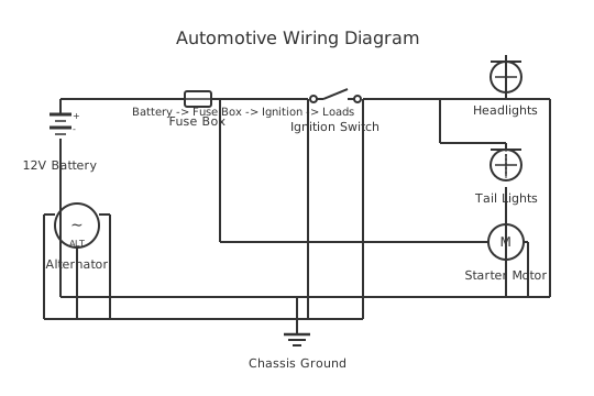
Understand how a Western-style snow plow electrical system connects the vehicle harness, solenoid block, pump motor, and controller to raise, lower, and angle the blade.
A Western-style snow plow electrical system is more than just a few wires to a winch. It is a purpose-built, high-current DC circuit that must survive vibration, submersion, road salt, and repeated thermal cycling across an entire winter season.
At the heart of the system sits the hydraulic power unit — a 12 V DC motor driving a gear pump that pressurises fluid to a manifold block fitted with solenoid valves. Each solenoid valve is a normally-closed, two-position electro-hydraulic switch. When the controller energises a solenoid coil, the valve opens and routes fluid to a specific hydraulic cylinder: the lift ram for blade height, and one or two angle cylinders for left/right movement.
The vehicle wiring typically divides into three harness segments. The first is the power/ground harness running heavy-gauge cable (commonly 4 AWG or larger) directly from the battery through an inline fuse or circuit breaker to the pump motor solenoid (a high-current relay). The second is the control harness, a lighter multi-conductor cable carrying low-current switched signals from the cab-mounted joystick or rocker controller to each hydraulic solenoid coil. The third is the headlamp isolation harness, which reroutes or supplements the vehicle's existing front lighting so the plow-mounted lamps become active when the plow is connected and the OEM lamps remain functional when it is removed.
The pump motor itself draws surge currents of 150–250 A or more during stall or cold-start conditions. This is why the main power feed must be fused at or near the battery with a high-interrupt-capacity fuse or a manual reset circuit breaker rated for that inrush. Undersized wiring here causes voltage drop that starves the motor, overheats cables, and can weld solenoid contacts closed — a safety hazard that leaves the blade stuck in a raised position.
Connectors between the truck and plow are normally weatherproof multi-pin plugs (commonly 9-pin or 11-pin round connectors in commercial designs) that separate cleanly when the plow is dismounted. Pin assignments vary by manufacturer and model family; always consult the specific wiring diagram for the exact harness generation in use. This article presents the generic topology and is for educational reference only. Any installation or repair must follow the OEM service documentation and applicable electrical codes.
How to wire western snow plow wiring diagram
- Disconnect the vehicle battery before starting any wiring work Remove the negative terminal first, then the positive. This prevents accidental short circuits through tools during installation. On trucks with dual batteries, disconnect both banks. Tape over the terminals while working.
- Route and secure the main power cable from the battery to the motor contactor Use the cable gauge specified by the plow manufacturer — 4 AWG is a common minimum, but high-performance commercial units may require 2 AWG or larger. Install the inline fuse or circuit breaker within 45 cm (18 inches) of the battery positive terminal. Route the cable away from exhaust components and secure every 30–40 cm with appropriate clamps. Never run power cable alongside brake lines.
- Mount the contactor (main power solenoid) in a protected location under the bonnet The contactor body should be protected from direct water spray and road debris. Mounting it near the battery shortens the high-current cable run. Ensure the coil control wires are routed separately from the main power cable to avoid inductive interference.
- Install the control harness from the cab controller to the plow connector Fish the multi-conductor control harness through the firewall using an existing grommet. Avoid creating new holes where possible to preserve the factory weather seal. Secure the harness to existing looms and away from moving parts such as the steering column and pedal assembly.
- Connect the plow-side harness to the solenoid valve block and pump motor With the plow dismounted, connect each solenoid coil wire per the colour-code in the OEM wiring diagram. Verify polarity — most coils are not polarity-sensitive but the motor and position sensors are. Apply dielectric grease to all connector pins before mating.
- Install the headlamp isolation harness Follow the manufacturer's instructions exactly for the vehicle make and model year. On CAN-bus equipped vehicles, load detection by the BCM can trigger fault codes if lamps are switched via simple relays. Use the harness designed for the specific vehicle to avoid dashboard warning lights.
- Reconnect the battery and test all functions before field use Test raise, lower, angle-left, and angle-right. Check that the pump motor de-energises immediately when no function is active. Verify headlamps switch correctly. Measure voltage at the motor terminals during operation — a drop exceeding 0.5 V under load indicates a wiring or connection problem that must be resolved before use.
Specifications
| System voltage | 12 V DC (standard vehicle electrical system) |
|---|---|
| Pump motor surge current (typical) | 150–250 A (varies by pump size and hydraulic load; measure with clamp meter) |
| Recommended main power cable gauge (minimum) | 4 AWG — consult OEM specification for specific model |
| Main fuse rating (typical range) | 150–300 A ANL or MIDI type — must be positioned within 45 cm of battery positive |
| Solenoid coil voltage | 12 V DC |
| Solenoid coil resistance (typical) | 8–20 Ω — confirm against OEM coil specification for the specific valve model |
| Acceptable voltage drop across main power circuit under load | Less than 0.5 V (battery terminal to motor terminal) |
| Multi-pin connector pin count (common configurations) | 9-pin or 11-pin round weatherproof — verify for specific plow model and generation |
Safety warnings
- DISCONNECT THE BATTERY before commencing any wiring work. The pump motor circuit carries high surge currents capable of welding tools to the battery terminals and starting fires if accidentally shorted.
- Always fuse the main power cable within 45 cm (18 inches) of the battery positive terminal. An unfused or improperly fused cable between the battery and the first load is an unprotected fire hazard in the event of a downstream short circuit.
- Do not substitute the OEM headlamp isolation harness with generic relays on vehicles equipped with body control modules (BCMs) or CAN-bus lamp management. Incorrect lamp loads can corrupt CAN data, trigger fault codes, and disable safety-critical vehicle functions.
- A raised plow blade stores gravitational potential energy. Before working under or near the blade for any reason, lower it fully to the ground and confirm the hydraulic system is de-energised. Never rely on hydraulic pressure alone to support a raised blade.
- This diagram and description are for general educational reference only. Installation and service of snow plow electrical systems must follow the plow manufacturer's official wiring diagrams, the vehicle manufacturer's electrical service manual, and applicable regulations. Consult a qualified automotive electrician for any work beyond your competence.
Tools needed
- Digital multimeter (voltage, current clamp, resistance)
- Crimping tool rated for the cable gauges in use (ratchet crimp for 4 AWG and larger)
- Wire stripper (heavy gauge capable)
- Torque wrench for battery terminal and solenoid stud fasteners
- Plastic panel removal tools (for cab firewall routing)
- Cable ties and cable tie mounting bases
- Heat-shrink tubing and heat gun
- Dielectric grease applicator
Common mistakes
- Using undersized power cable: A 10 AWG cable on a system that requires 4 AWG will overheat under motor load, drop voltage to the pump, and eventually fail or cause a fire. Always match cable gauge to the OEM specification and the measured current draw.
- Grounding the pump motor to a painted surface: Paint is a poor conductor. Any ground connection to the vehicle chassis must bite into bare metal, preferably at an existing factory earth stud. A high-resistance ground causes exactly the same symptoms as undersized positive wiring — slow operation and overheating.
- Omitting the main fuse or positioning it too far from the battery: The cable between the battery positive and the first fuse is unprotected. If that length of cable chafes and shorts, there is nothing to interrupt the fault current except the battery itself, which can sustain arc faults long enough to ignite vehicle wiring.
- Skipping dielectric grease on the plow connector: Plow connectors spend weeks buried in wet snow and road salt. Without dielectric grease on every pin, corrosion builds up within one season and causes intermittent function failures that are difficult to diagnose.
- Confusing solenoid coil wires and swapping functions: If lift and angle solenoids are transposed, the controller commands will produce incorrect blade movements. Always verify each function against the colour-code chart in the OEM wiring diagram before reassembling the harness.
- Failing to test voltage drop under load: A system that appears functional at rest may suffer significant voltage drop during operation. Measure voltage at the pump motor terminals with the motor running; more than 0.5 V drop across the power circuit indicates a resistance problem in the cables or connections.
Troubleshooting
- Blade does not move in any direction; pump motor does not run
- Cause: No power reaching the pump motor — blown main fuse, failed main contactor, broken power or ground cable, or discharged battery Fix: Check battery voltage (should be above 12.4 V at rest). Test fuse continuity. With the controller commanding a function, probe the contactor output terminal for battery voltage. If voltage is present at the contactor output but absent at the motor, the cable between them is open. If voltage is absent at the contactor output, probe the coil control circuit to confirm the contactor is being energised.
- One hydraulic function (e.g. angle right) does not work; others function normally
- Cause: Faulty solenoid coil, broken coil wire, corroded connector pin for that specific solenoid channel, or failed controller output for that channel Fix: Disconnect the plow harness connector. Measure resistance of the suspect solenoid coil between its pin and the ground pin. Compare to OEM specification. If coil resistance is correct, probe for switched voltage at the controller output for that function. If voltage is present but coil resistance is infinite (open circuit), the wire between connector and coil is broken.
- Plow headlamps do not illuminate or vehicle dashboard shows lamp fault codes
- Cause: Incorrect lamp isolation harness fitment, blown lamp fuse in plow harness, or BCM detecting unexpected lamp load on a CAN-managed circuit Fix: Verify the isolation harness part number matches the vehicle make, model, and year. Check for blown fuses in the plow harness fuse block. On BCM-equipped vehicles, scan for stored fault codes before assuming the harness is wired incorrectly — a pre-existing lamp fault can be exacerbated by the added load of plow lamps.
- Pump motor runs continuously even when no controller function is commanded
- Cause: Main contactor contacts welded closed (caused by repeated high-inrush switching without adequate fuse rating) or controller output stuck in active state due to a faulty controller or shorted coil wire Fix: Disconnect the contactor coil control wire. If the motor stops, the controller or a wiring short is holding the contactor energised. If the motor continues with the coil wire disconnected, the main contacts are welded — replace the contactor immediately. Do not operate the plow with a welded contactor as it will keep the pump running and can cause hydraulic overheating.
- Intermittent operation — plow works some of the time but cuts out under load
- Cause: High-resistance connection at the battery terminals, ground strap, main fuse holder, or plow connector pins; voltage drop causes the contactor to drop out under load Fix: Clean and re-torque all high-current connections starting from the battery terminals. Apply dielectric grease to the plow connector. Measure voltage at the motor terminals during operation — if it drops below 10 V, trace back through the circuit to find the high-resistance joint. A thermal imaging camera or an infrared thermometer is useful for identifying hot joints under load.
Frequently asked questions
Why does my plow only lift slowly in cold weather?
Cold hydraulic fluid is thick, increasing pump load and motor current draw. Combined with a marginal battery or undersized wiring, voltage drop across the power cables starves the pump motor. Check battery state of charge, clean all ground connections, and verify cable gauge meets the OEM specification. A dedicated battery or a dual-battery isolator system is the permanent fix for working trucks.
What does the main power solenoid (contactor) do?
The main solenoid is a heavy-duty relay — typically rated 200 A or more — that sits between the battery positive cable and the pump motor. When any hydraulic function is requested, the controller energises the solenoid coil, closing the high-current contacts and powering the pump. This avoids running full motor current through the cab controller and allows the system to de-energise the motor automatically when no function is active.
Can I splice into the existing headlamp circuit instead of using an isolation harness?
This is a common shortcut that typically violates the vehicle OEM's wiring guidelines and can overload the BCM-controlled lamp circuits on modern vehicles. The correct approach is the manufacturer-supplied isolation harness, which either switches the OEM lamps off when plow lamps are active (relay-switched isolation) or uses a dedicated relay to add the plow lamps without drawing through the factory circuit.
How do I find a short in the solenoid coil wiring?
Disconnect the multi-pin connector at the plow. Using a multimeter set to resistance (ohms), measure each solenoid coil pin against the ground/return pin. A healthy coil reads 8–20 Ω depending on rating. A reading near zero indicates a shorted coil or a shorted wire to ground. Open-circuit (OL) indicates a broken coil or broken wire. Refer to the OEM coil resistance specification for the exact expected value.
Is it safe to leave the plow control harness powered when the plow is dismounted?
The truck-side harness connector should be capped with the provided weatherproof dust cap whenever the plow is off the truck. Leaving live pins exposed risks corrosion and accidental short circuits. Some systems include a relay that cuts power to the harness when the plow plug is disconnected; verify this feature in your specific wiring diagram.
Related diagrams
- western plow wiring diagram
- western plow wiring harness
- boss plow solenoid wiring diagram
- boss plow wiring diagram
- boss plow wiring harness
- fisher plow wiring diagram