Single-Line Diagram Software
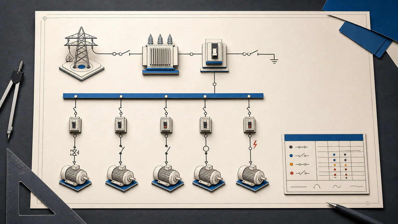
A single-line diagram (SLD or one-line diagram) shows how electrical power moves from sources through transformers, protection, buses, feeders, panels, and loads. CircuitDiagramMaker turns those symbols into structured objects so a change to a load, cable, or breaker also updates the schedules and checks built from the drawing.
Product scope reviewed: 2026-07-30. This is a first-party capability review, not an independent engineering certification.
- electrical symbols
- 480+
- live engineering reports
- 10
- supported analysis modes
- 3

What belongs on a useful one-line diagram?
A useful SLD communicates the source of supply, nominal voltage and phase, major distribution equipment, protection, conductor or cable information, and the connected loads. It should be readable as a power path—not merely a collection of symbols. CircuitDiagramMaker keeps each device and connection selectable, searchable, and tied to engineering properties.
- Utility, generator, UPS, battery, and renewable sources
- Transformers, busbars, switchboards, panels, and disconnects
- Breakers, fuses, protective devices, feeders, motors, and other loads
- Voltage, phase, power, current, conductor, route, and location data
Drawing and schedules share one data model
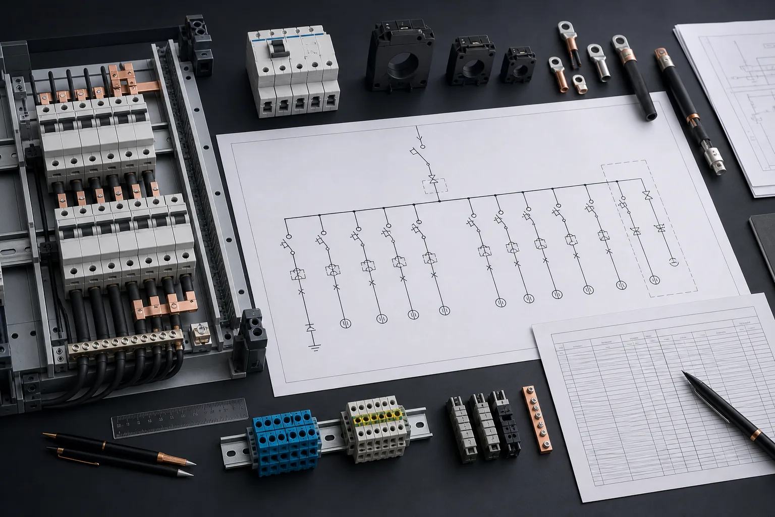
The drawing is the source of truth. Device tags, manufacturer data, catalog numbers, load ratings, wire numbers, cable cores, and terminals live on the objects rather than in a separate spreadsheet. Live reports group that data into device lists, wire lists, cable schedules, terminal plans, load schedules, panel placement data, PLC I/O, and coil/contact cross-references.
- Import device properties, cable schedules, and terminal plans from UTF-8 CSV
- Export any live report as CSV without re-keying the drawing
- Find and replace tags, values, part numbers, descriptions, wire numbers, or net labels across sheets
- Save reusable rated devices to a shared project library
Calculations are visible, bounded, and reviewable
For loads with sufficient data, the editor calculates current for one-, two-, or three-phase systems and proposes the next standard breaker rating using a design margin. Feeder voltage drop is calculated from current, route length, cross-section, material, voltage, and phase count. These are transparent workflow aids, not hidden compliance claims.
- One-, two-, and three-phase current calculation
- Demand factor, power factor, and efficiency fields
- Copper, aluminium, or user-classified conductor material
- Voltage-drop result in volts and percent
Trace the complete source-to-load path
An SLD is most useful when reviewers can follow every load back through its feeder, protective device, bus, transformer, and source. The document check traverses structured connections rather than estimating from nearby shapes. It can therefore flag a load with no complete source path or no protective device in that path while leaving engineering judgement visible to the reviewer.
- Connection traversal uses registered component pins and wires
- Protective-device presence is checked along the actual path
- Voltage and phase mismatches are reported as named issues
- Cross-sheet paths remain explicit through off-page connectors
Keep the issue drawing and feeder schedule aligned
A one-line drawing often changes during review: a breaker rating, conductor size, route length, device tag, or connected load is revised. Because the schedule reads the same objects, those changes do not require a second spreadsheet edit. Revision comparison and immutable releases make the change visible without claiming that a calculation has been independently certified.
- Drawing and schedule values share the same stored fields
- CSV exports support review and downstream handoff
- Object-level revision comparison distinguishes changed data
- Issued releases preserve the exact reviewed snapshot
Catch documentation defects before issue
The engineering check scans the structured document rather than guessing from pixels. It identifies duplicate or missing tags, orphan wires, duplicate wire numbers, missing conductor sizes, voltage and phase mismatches, loads with no complete source path, and loads with no protective device in that path. Every finding names the affected object and severity.
- Deterministic checks produce the same result from the same drawing
- Warnings and errors remain separate from certified engineering studies
- Revision comparison shows added, removed, and modified drawing objects
- Immutable releases preserve the exact issued project snapshot
Use it for documentation-sized SLD work
The browser workflow is designed for concept diagrams, equipment schedules, small and medium distribution documentation, tender drawings, training material, and as-built updates where speed and synchronized schedules matter. Use a dedicated power-system study package when the job requires short-circuit, load-flow, arc-flash, harmonic, or protection-coordination analysis.
- Commercial and light-industrial distribution
- Motor-control and equipment feeder diagrams
- Generator, UPS, and changeover documentation
- Training, tender, maintenance, and as-built records
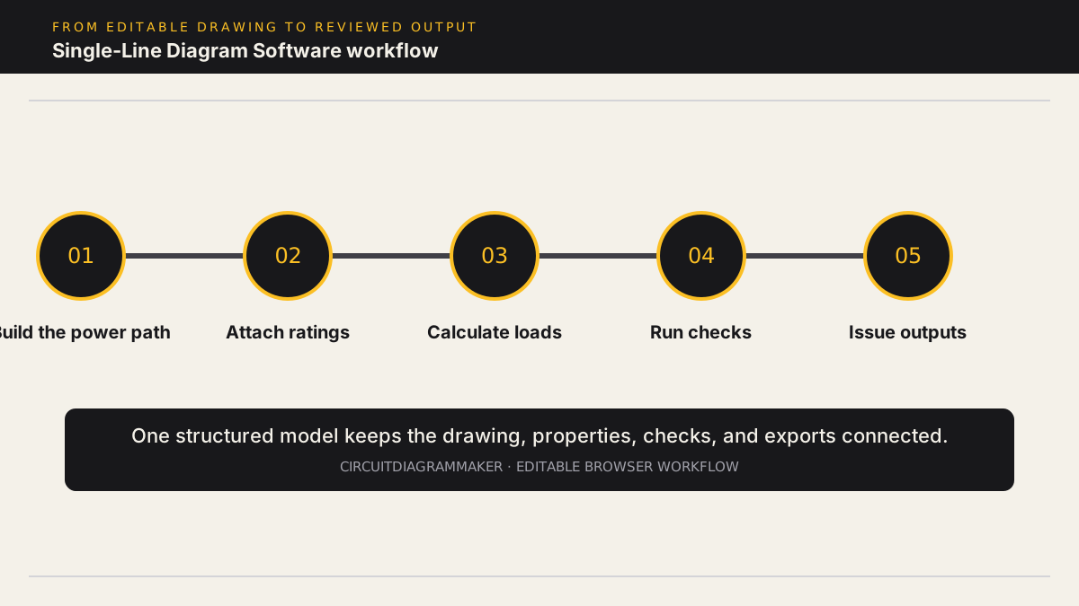
Workflow
- Place sources, transformers, protective devices, buses, panels, motors, and loads from the electrical symbol library.
- Record system voltage, phase count, connected power, demand factor, route length, conductor material, and cross-section.
- Calculate load current, a standard breaker suggestion, and metric conductor voltage drop from the data on the drawing.
- Run data-integrity checks for missing ratings, mismatched voltage or phase, incomplete source paths, and unprotected loads.
- Export the diagram together with device, load, wire, cable, and feeder-ready CSV schedules for review or handoff.
Deliverables
- Drawing package: Multi-sheet drawing with title blocks, revisions, notes, layers, and PDF, SVG, PNG, or DXF output.
- Load schedule: Connected and demand power, phase, voltage, calculated current, and breaker-rating fields.
- Feeder data: From-to endpoints, conductor size, material, length, cable/core data, and voltage-drop results.
- Review evidence: Issue list, anchored comments, revision comparison, audit events, and immutable releases.
Current limitations
- The SLD checks are deterministic data-integrity checks, not a certified short-circuit, arc-flash, load-flow, harmonic, or protection-coordination study.
- Regional code compliance is not asserted. Breaker suggestions use a configurable design margin and require professional verification.
- Voltage drop requires current, voltage, conductor material, cross-section, and route length; incomplete inputs do not produce a result.
Capability sources
- Product capability matrix
- Simulation model compatibility
- Physical component library and verification states
Related electrical design workflows
Frequently asked questions
What is the difference between a single-line and a wiring diagram?
A single-line diagram simplifies a multi-phase power system into one line per circuit or feeder. A wiring diagram normally shows individual conductors, terminals, and physical connections in more detail.
Can I make a single-line diagram online for free?
Yes. The browser editor can be opened without a download and the starter plan can be used to draw and export diagrams. Account and plan limits apply to saved projects, symbols, and exports.
Does it calculate fault current or arc flash?
No. The SLD workspace calculates supported load-current and voltage-drop cases and performs documentation checks. It does not replace certified fault, arc-flash, load-flow, or protection-coordination software.
Can I export an SLD to AutoCAD?
The editor exports DXF vector geometry for CAD workflows, as well as PDF, SVG, and PNG. It does not import or preserve native DWG intelligence.
Open a lighting-panel sample or review the capability matrix.