Electrical Control Panel Design Software
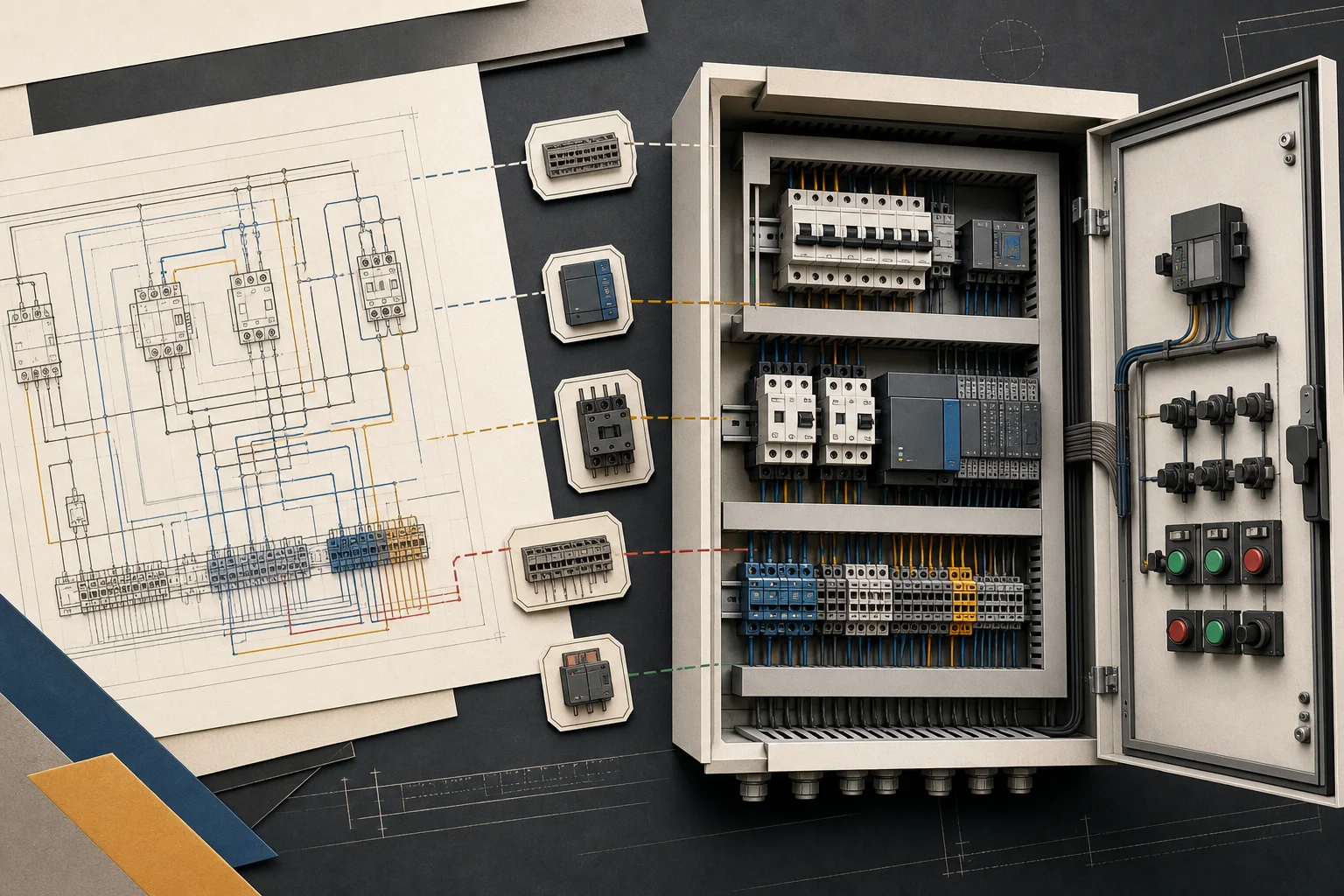
Electrical control panel design joins two views of the same system: the functional schematic and the physical enclosure. CircuitDiagramMaker keeps device tags, part data, terminals, PLC addresses, wire numbers, footprints, and panel coordinates on one model so documentation can update without rebuilding disconnected spreadsheets.
Product scope reviewed: 2026-07-30. This is a first-party capability review, not an independent engineering certification.
- industrial symbols
- 160
- synchronized enclosure views
- 2D + 3D
- 3D visualization export
- GLB

Move from functional design to build documentation
A control schematic explains how power, control, safety, and I/O functions interact. The panel view answers where those devices are mounted. CircuitDiagramMaker connects the two with stable object IDs and device tags, so the schematic data can drive reports and a synchronized 2D backplate view.
- Contactors, overloads, starters, VFDs, PLCs, safety relays, terminals, and pilot devices
- Multi-sheet documents with off-page connectors, title blocks, revisions, notes, and layers
- Coil/contact parent-child data and cross-reference schedules
- Footprint width, height, mounting type, rail, and panel coordinates
Automate repetitive electrical documentation
The Engineering workspace fills missing structured data while preserving manual work. It can assign reference tags by electrical device family, number unnumbered wires without collisions, calculate supported loads, allocate PLC input and output addresses, generate paired terminal records, and insert reusable motor-control circuits as one undoable action.
- Automatic component/reference tagging for missing device tags
- Sequential wire numbering that preserves existing numbers
- PLC I/O addressing for recognized sensors, switches, coils, lamps, solenoids, and motors
- Reusable project device records and circuit macros
Generate the reports a panel shop actually reads
Live reports are built from the same devices and connections visible on the canvas. Along with device and wire lists, the workspace produces cable, terminal, PLC I/O, load, panel, label, splice, and coil/contact cross-reference schedules. CSV import updates existing devices by tag without replacing drawing geometry.
- Device/BOM schedule with quantity and catalog data
- Wire and cable from-to schedules with terminations
- Terminal and PLC I/O plans
- Wire-marker, device-label, terminal-label, and splice schedules
Check the enclosure before handoff
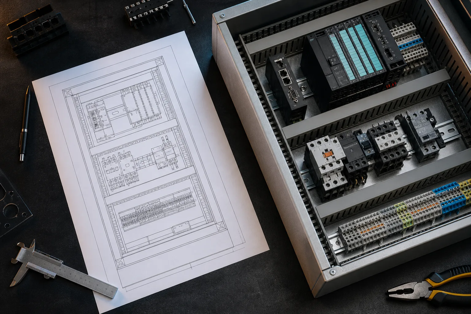
Footprint-backed devices can be placed automatically inside a configured enclosure. The 2D view highlights overlap and boundary problems; the synchronized WebGL view turns the same width, height, depth, mounting, and X/Y records into an orbitable 3D enclosure and GLB visualization export.
- Configurable enclosure width, height, and depth
- DIN-rail, backplate, door, and other mounting classifications
- Collision, overflow, utilization, and selected-device highlighting
- GLB handoff without pretending to generate native STEP or Parasolid MCAD
Compare four panel layouts before applying one
Auto-arrange produces alternative placements instead of silently overwriting the panel. Wiring-first clusters electrically connected devices to reduce estimated same-surface route distance. Compact footprint preserves free area, functional zones group device families, and service access uses roomier lanes. Each option reports estimated wire length, envelope use, collisions, overflow, unplaced items, and DIN-rail mounting issues.
- Wiring-first, compact, functional-zone, and service-access strategies
- Preview and cycle through alternatives before applying
- Move devices manually and rescore the adjusted option
- No claim that a numeric score replaces heat, access, or code review
Create dimensioned components when catalogs differ
A panel tool cannot assume every contactor, PLC, enclosure, or terminal has the same dimensions. Devices can carry manufacturer and catalog identifiers together with editable width, height, depth, mounting type, panel surface, terminal roles, and custom fields. Starter profiles make placement faster, while visible verification states distinguish generic geometry from exact source-checked part data.
- Editable device envelope and depth
- DIN rail, backplate, door, duct, terminal, and other mounting classifications
- Schematic symbol linked to compatible physical profiles
- Exact manufacturer claims require the corresponding datasheet and review
Review, release, and preserve what was issued
Team roles separate owners, administrators, editors, and viewers. Reviewers can anchor comments to drawing objects, assign actions, compare revisions, and submit work for review. A release is an immutable, content-addressed snapshot of the project, which makes later changes distinguishable from the issued package.
- Live collaboration and anchored review comments
- Assigned open or resolved review actions
- Revision diff and restore
- Sequential immutable project releases
Workflow
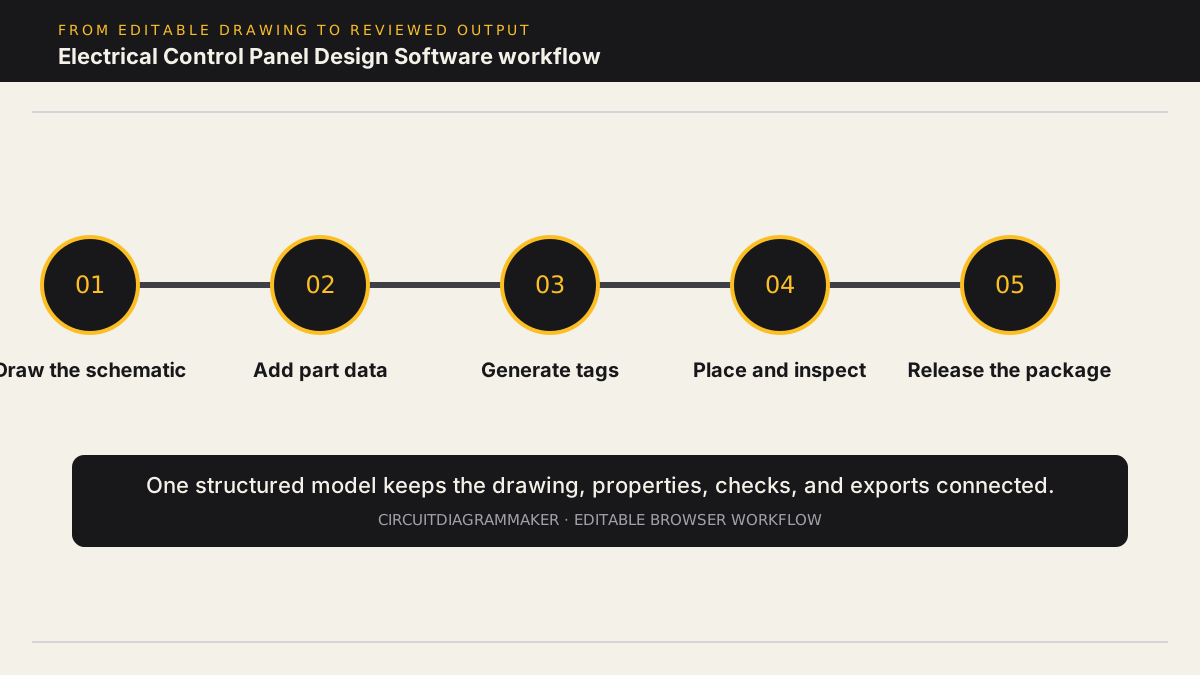
- Start from DOL, star-delta, reversing, seal-in, or safety-circuit templates and reusable circuit macros.
- Add manufacturer, catalog number, rating, terminal, footprint, mounting, rail, and installation-location data.
- Generate missing device tags, number missing wires, assign PLC I/O addresses, and build a terminal plan.
- Generate device, BOM, wire, cable, label, splice, terminal, PLC I/O, and coil/contact reports from the drawing.
- Auto-place footprint-backed devices, check overlap or overflow, inspect the synchronized 3D enclosure, export GLB, and issue a reviewed project release.
Deliverables
- Control schematics: Multi-sheet power, control, safety, PLC, and terminal drawings with reusable circuits.
- Panel layout: Synchronized 2D placement and interactive 3D enclosure visualization with footprint, overlap, boundary, selection, and GLB export.
- Build schedules: Device, wire, cable, terminal, PLC I/O, label, splice, load, and cross-reference reports.
- Release package: Printable project package, CSV reports, project JSON, revision evidence, and immutable release snapshots.
Current limitations
- The 3D enclosure is visualization geometry derived from panel records; it does not produce STEP/Parasolid, machining data, thermal studies, or mechanical cable routing.
- Thermal, creepage, clearance, SCCR, selective-coordination, and regional code-compliance studies are not automated.
- Automatic placement and rating suggestions are starting points and do not replace manufacturer installation instructions or professional review.
Capability sources
- Product capability matrix
- Simulation model compatibility
- Physical component library and verification states
Related electrical design workflows
Frequently asked questions
Can I design both the schematic and panel layout?
Yes. Devices carry schematic properties plus physical footprint, depth, mounting, and placement data. The checked 2D view and interactive 3D enclosure are generated from the same records.
Does it number wires and component tags?
Yes. The Engineering workspace can fill missing device reference tags and wire numbers while preserving existing manual identifiers.
Can I generate PLC and terminal documentation?
Yes. Recognized I/O devices can receive PLC addresses, wires can generate paired terminal records, and both PLC I/O and terminal plans are available as live CSV reports.
Is this a complete replacement for EPLAN or AutoCAD Electrical?
It covers browser-based schematic, report, review, 2D panel documentation, and 3D visualization workflows. Large catalogue ecosystems, native DWG or STEP editing, mechanical routing, and certified engineering studies still require specialist desktop or enterprise tools.
Open a control-panel sample or review the capability matrix.